 Hi, readers welcome to another post. In this post, we will have a detailed look at Introduction to Linear Series Regulators. The basic type of voltage regulator is a linear regulator and switching regulators. These 2 regulators exist in the form of ICs. 2 basic categories of linear regulators are mentioned here the first one is the series regulator and the second one is a shunt regulator.
In this post, we will have a detailed look at the circuit and other related factors of linear series regulators. So let’s get started with Introduction to Linear Series Regulators.
Introduction to Linear Series Regulators
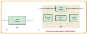
- In below figure you can see the basic configuration of the linear regulator denoted as the main element used in the circuitry can be seen in figure denoted as b
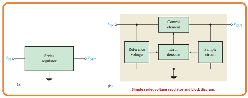
- The control component is pass transistor in series combination with the load among the input and output.
- The output circuitry detects a variation in the output voltage. The faults sensor does a comparison between the sample voltage and a reference voltage and causes the controlling component to do compensation for maintaining the constant output voltage.
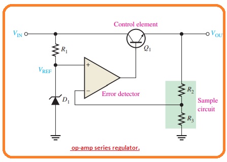
- The basic operational amplifier series regulator is drawn in below figure.
Regulating Process
- The function of the series regulator is explained in the below figure.
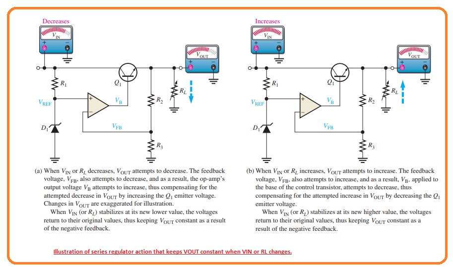
- The resistive voltage divider circuitry created with resistance R2 and R3 and detect the variation in the output voltage.
- when the output gets decreases as shown in the above figure since the decrement in the Vin and increment in the current IL causes due to the decrement int he resistance RL.
- The proportionate voltage reduces is given to the operational amplifier inverting terminal with the voltage divider.
- As the Zener diode keeps the other operational amplifier input at close to the constant reference voltage the minor different voltage is created about the operational amplifier inputs.
- this difference voltage is get amplified and the operational amplifier output voltage VB increases.
- This increment is given to the base of the transistor Q1 causes the emitter voltage to reises until the voltage at inverting input becomes equal to the reference voltage.
- This process offsets the attempted decrement in the output voltage and maintaining it at a constant level.
- The power transistor Q1 is normally used with the combination of heat sink since it can handle the load current.
- The reverse process exists when the output goes to the increment as can be seen in figure denoted as b.
- The operational amplifier in the series regulator is linked as a noninverting amplifier here reference voltage is the input voltage at the noninverting terminal and the R2/R3 voltage divider creates the negative feedback circuitry.
- The closed-loop voltage gain is given as.
Acl = 1 +R2/R3
- So the regulated output voltage of the series regulator is given as.
VOUT=(1+R2/R3)VREF
- According to this analysis, we can observe that the output voltage is found with Zener voltage and the resistance R2 and R3
Short-Circuit Protection
- If the large quantity of load current flows the series pass transistor can be get damaged.
- Mostly regulators use some category of large current protection in the shape of current limiting phenomena.
- The below figure one technique of current limiting to stop the overload current is used.
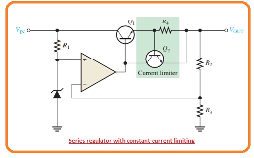
- The current limiting circuitry comprises of transistors Q2 and resistance R4.
- The load current passing in the resistance R4 generates a voltage from base to emitter of transistor Q2.
- When the IL current goes to the already find extreme value the voltage loss about resistance R4 is enough to forward bias the base-emitter junction of transistor Q2 and cause it to operate.
- Certain operational amplifier output current is moved transistor Q2 to decrease Q1 the base current therefore IL is restricted to its extreme point IL(max).
- As the base-emitter voltage of transistor Q2 cannot larger than 0.7 volts the voltage about resistance R4 kept a constant level and the load currently restricted to the
IL(max)=0.7 V/R4
Regulator with Fold-Back Current Limiting
- In the earlier current limiting method, the current is limited to the extreme contact point.
- Fold back currently restricted is a technique used in high current regulators where the output current in overload situations loss tot he points less than the peak load current.
- The main principle of fold back current is restricted as with the below figure.
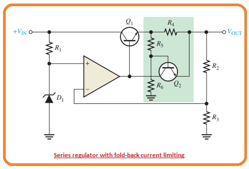
- The circuitry in the green closed area is like to the constant current limiting configuration.
- The voltage loss created about the resistance R5 and R6.
- The voltage loss created about the load current should not only cover the base-emitter voltage needed to on transistor Q2 but it should also cover the voltage loss about the resistance R5. SO voltage loss about the R4 will be given as.
VR4 = VR5 + VBE
What are the basic linear series regulators?
- The series regulator operated by providing a path from the supply voltage to load through variable resistance normally transistor. It is at the upper half of the voltage divider and the lower half of the load.
What are the main types of regulators?
- Linear Regulators.
- Switching Regulators.
- LDO Regulators.
- Step-Down and Step-Up Converters.
- Buck-Boost Converters
What is the structure of a linear regulator?
- The linear regulator comes with 4 main components output driver transistor, reference voltage unit, feedback resistor and error amplifier.
What is the efficiency of a linear regulator?
- If the input voltage is over the output value, the linear regulator can be about 95 percent to 99 percent efficiency.
Read also
That is all about the Linear Series Regulators i tried my level best to make it simple for you. thanks for reading. Have a good day.