 Hello, readers welcome to the new post. In this post, we will have a detailed look at What is Through Hole Technology. PCB board is the main element of any circuitry that we have in our common life. Its main types are single layer PCB, double layer, multiple layers that are constructed according to the use of the project. the design and creation of this board is the very caretaking process if there is no certain parameters are taken its manufacturing can cause serious problems and damage our design. So there are different techniques are used to make these boards and certain parameters are taken into consideration for the creation of the board.
In this post, we discuss the through-hole technique used in the manufacturing process of PCB board. So if you are going to use this technique in your project and want to get this facility must reach our the PCBWAY. that are offering services related to through-hole techniques with reasonable prices and high-quality techniques with well-furnished equipment used to make through this process. They also offered full customer support to their users and fulfill all details and queries related to their services. So let get started with
What is Through Hole Technology
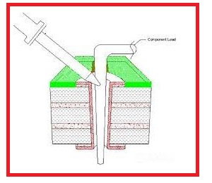
- The through-hole technique is the method that used to assemble the different component on the PCB board through the use of leads that helps to place the component on the board.
- After putting the components on the board are connected through the soldering process.
- with the passage of time, this technique has become very common has replaced the older methods used like the point-to-point assembly process.
- After 1950 when 2nd generation of computers designed that method has become very popular to the electronic industry.
- This technique helps to make PCB traces on both sides after that now multiples layers of the board are designing through this tool.
- This method for connection of components is mostly preferred for such a structure where high reliability is needed.
- It mostly used in military devices, aviation components or for such places where high temperature exists.
- For different types of testing and prototyping applications, it preferred to use.
through Hole Technique Leads
- In this technique, elements are configured through the use of leads. The leads used in this technique are axial and redial.
- The configuration of axial leads is that they are separated like cylinder shape through the axis of component used.
- Their physical dimension is like the jumpers wire and placed at small distances on the board.
- While radial leads are configured in parallel sharp at the area of the board.
- these leads are like the radius of the circle over which different elements are configured to make circuitry.
- When radial leads are used they make structure at ninety degrees and offered the high-density structure and employed in the board struggling instruments where high operating speed is needed for component connections.
- If there is such a design where we have to transform the axial connected elements in the radial form just move the LEaDs in the U shape.
- During this process make surer that no physical connection occurs in the components assembled on board.
PCBWAY Through Hole Features
- The main features offerd by the PCBWAY are mentieond
- In these techniques, high strength offered to connection making as compared to other techniques like SMT where extra cost needed for drilling.
- They offer the limiting routing place to trace the signal at layers when we are working on the multiple-layer board.
- The through-hole technique generally employed in the creation of large size components projects such as semiconductor, capacitors with the packing of T0-220
- They also supported this technique in the manufacturing of the plug connectors’ electromechanical relays
- in case of design through-hole is used over the surface mounted to make different prototyping modules.
Through Hole Is Cost-Effective Process
- The main benefit to use this technique is there no creation of newly solder stencil again and again that saves cost.
- This process helps to save a high-level amount that generally needed in the use of other types of techniques.
- In the case of SMT, there is needed for different components again to use for a design that makes it costly.
- When this process is completed the circuit testing is done through a manual process that also saves the amount used for special types of tests.
- There is the use of another less expensive process in this technique that is the surface metallic process through use of tin-lead solder.
- This process also helps to observe the problems like additional bends and twists in the final board and no need to make a new design.
Advantages of Through Hole
- The main benefits of this technique are mentioned here.
- As compared to the SMT the connection configuration among the board and through-hole component is very stronger.
- Due to stronger connection and grip, it Prefers for such environments where high mechanical strength is needed.
- It used in an environment large temperature exists..
- It used in the construction of different types of transformer and connectors.
- Its testing process is easy than other techniques.
Disadvantages of Through Hole
- With the advantages, there are some drawbacks of this technique that must also take into consideration before use this method.
- As the elements in this technique are passed in the board for this hols are created on the board that is a costly process.
- Its other disadvantage is that offered a limited area for elements at one side of the board and decreases the place for the creation of multiple layers.
- Its solder points show less reliability than the other techniques
So that is a detailed post about the Through Hole Technology i tried to cover each and every related parameter. I also suggest the Through Hole Technology services providers. If you have any further query ask in the comments. Thanks for reading have a nice day


