 Hi students welcome to the new tutorial. In this post we will discuss the balanced three-phase system. There is 3 phases that are used to transmit the power from one place to other in the electrical system. The system that has the same value of current and voltage in every wire is called a balanced system but this current and voltage have one twenty-degree phase difference.
In this post, we cover all detailed parameters related in the balanced three-phase system and see how these are important in the electrical system
Introduction to Balanced Three-Phase System
- In the case of the phase balance system, the values of current voltage can be found at any location in the system through the use of equivalent circuitry.
- This phenomenon is mention here.
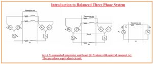
- The below diagram indicates in this circuity generator is delivering power to such load that is also in wye connection arrangements like a generator.
- In the case of a balanced system, there can be use of neutral wire but will affect the system due to the balance system 0 current flow in that wire. Can see in a diagram denoted as b
- We can see that there is every phase has the same value with angle difference of one-twenty degrees.
- In this system, there is easy to discuss the behavior of one phase and after that compare it other phases to see the results that will be similar.
- This process is shown in the above figure denoted as c
- Here is neutral wire is a link to send the current flow to the generator from the load.
- But in case of there is no need of this wire in the delta connection
How Delta Connected Load Add in System
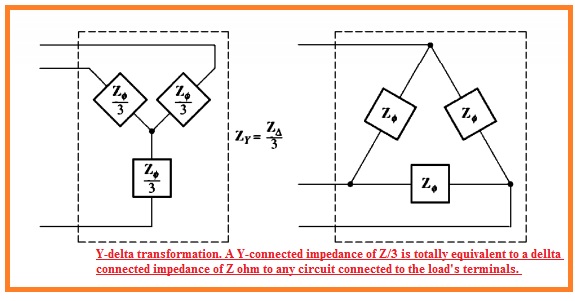
- The basic method is to change the impedances from the wye to the delta.
- In case of the certain loads that are in balance state for conversion of wye to delta transformation, there is same values of impedance exist having a value of Z and like to the wye connection load having impedance value for every phase is Z/3
- Here equivalence indicates that if load connected to this system will has the same values for current volts and power
What is Single line Diagram?
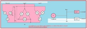
- In the balanced, three-phase system wire are configured that there is one load and one power source is linked to the single line.
- These 3 phases has the same value for current and volts with one twenty-degree phase change.
- Due to the same values for phases, it is easy to make a design or line of the system for three phases.
- This single-line diagram offered a detailed overview of all components used in the system.
- At this line, all components link to the system like motor, generators, lines, transformer, are shown.
What Is Power Triangle
- Let us suppose that for our transmission line impedance value is zero so some certain measures are done.
- These terms will be done for using the real and reactive power in case of every load to finds the current and p.f exiting at different points of the system
- For instance, let us assume that the power network is shown above the diagram. If the transmission line in this power system is free from any power loss so the voltage at the load side will be like to the voltage at the generator side.
- If there is a specif value for voltage at the generator that with the use of these values the parameters for P.F and other values of current and volts can be found. Using these points
- Finds the voltage for transmission and load ends will has the same value as no loss in the line.
- finds the real and reactive power for every load.
- In the thirds step find the net real and reactive power send to the load
- Finds the p.f of the network through use of the power triangle.
That is all about the Balanced Three-Phase System if you have any further query ask in the comments. Thanks for reading have a nice day


