 Hi, reader welcome to the new post. In this post, we will have a detailed look at the Introduction to Cumulatively Compounded Dc Generator. DC generator is an electrical machine that is used to convert mechanical power into DC electrical power. There are numerous categories of dc generators such as dc series generators, dc shunt generators, and dc wound generators.
All generators produce dc power but the difference is that their structure is a combination of their armature and field windings. These connection define their names. In this post, we will discuss the working, operation application, and related parameters of a cumulatively compound dc generator. So let’s get started with Introduction to Cumulatively Compounded Dc Generator.
Introduction to Cumulatively Compounded DC Generator
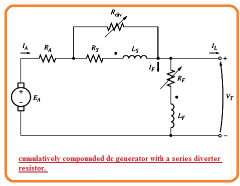
- The cumulatively compounded dc generator has such a combination of series and field windings that their net produced flux will be added to each other.
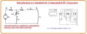
- In the below figure the equivalent circuit of this generator can be seen that has a long shunned configuration.
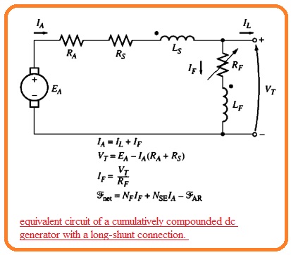
- The dot shown at 2 field windings is used to show the direction of the current that is towards it is positive. In simple words, the current moving to the dot indicates the positive value of MMF.
- Note that the armature current moves to the dotted point of series field winding and the shunt current IF moves to the dotted point of shunt field windings.
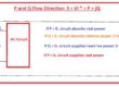
- So the net MMF for this equation is given here.
Fnet=FF+FSE-FAR
- Here FF denotes the shunt field MMF FSE indicates the series field MMF and FAR denotes the MMF due to the armature reaction.
- The equivalent effective shunt field current for this generator is mentioned here.
NFl’F = NFIF + NSEIA – FAR
I’F=IF+NSE/NF xIA-FAR/NF
- The equation of current and voltage for this generator is mentioned here.
IA=IF+IL
VT=EA-IA(RA+RS)
IF=VT/RF
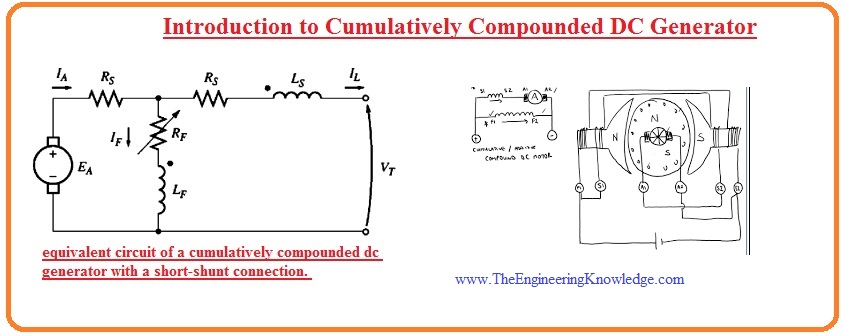
- There is a second connection linking of the cumulatively compound generator. That is a short shunt connection here the series field is at the outer side of the shunt field circuitry and IL is passing through this coil in place off IA.
Terminal Characteristics of Cumulatively Compounded DC Generator
- To discuss the terminal characteristic of cumulatively compound dc generators it is compulsory to study the competing effect which exists in the generator.
- Let us assume that the load at the generator rises. With the load, increment loads current IL increases.
- As IA=IF+IL the armature current also increases. At this stage, there are to factors that exist in the generator.
- AS current IA increases in results IA(RA+Rs ) losses also increase. That results in a decrement in VT.
VT = EA – IA (RA + Rs)
- With the IA increment, the series field magnetomotive force FSE=NSEIA rises also. It raises the net MMF that is Ftot=NFIF+NSEIA which causes an increment influx in the generator.
- Due to flux increment, internally generated voltage also increases that in results VT=EA-IA(RA+RS) increases.
- these 2 factors repel one another one causes to increment in VT and the other decreases the VT.
- SO here the question arises which effect dominates in the generator?
- This question answers that the number of turns in series to poles defines the effect.
- Different cases also explain this question.
- Some turn NSE: if there is less value of turns in series the resistive voltage loss effect wins hand down. The voltage decreases like in a shunt generator.
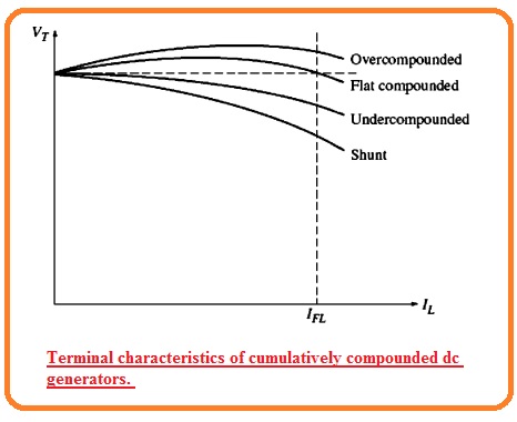
- This category of assembly where full load VT is less than the no-load Vt is known as undercounted
Large Series Turns:
- The second case is that if we add some more turned-in series to the poles then ist flux strengthening effect dominates and Vt increases with load.
- Though with the load increment magnetic saturation adjusts in and resistive losses become strengthened than the flux increase factor.
- In this generator, VT firstly rises and after that decreases with the load increment.
- If the terminal voltage for no-load has the same value as the full load then a generator is known as flat compounded.
EVEN more, series turns added:
- If even further series turns are connected with the generator the flux strengthening factor nominates for long time interval till then resistive losses dominate.
- This results in the characteristic having full load VT larger than the no-load VT.
- If the terminal voltage for fully loaded condition is larger than VT for no-load the generator state is known as over compounded.
This condition can be seen in the below figure.
- We can also discuss all these voltage characteristics for one generator in use of diverter resistance.
- In the below figure you can see the generator having a large number of series turns NSE.
- The diverter resistance is linkked to the ssereis field.
- If resistance Rdh is set to a larger value mostly part of IA will pass in the series field windings and the generator is overcompounded.
- If we change the value of resistance Rdiv to less value then a larger part of the current about series field windings passes through Rdiv this state of the generator is called uncompounded.
Voltage Control of Cumulatively Compounded DC Generators
- The methods used for voltage control of cumulatively compound dc generators are similar to those used for shunt DC generators.
- Vary the rotation speed. The increment in W results in increases in internal generated voltage EA=KφW that causes the increment in terminal voltage.
- Vary Field current: The decrement in RF results increment in field current that raises the net MFF of the generator. With the Ftot rises flux in the generator increases and internally generated voltage increases. That results in an increment in Internal generated voltage.
Analysis of Cumulatively Compounded DC Generators
- The below-written equations A and B are the main descriptions of the terminal characteristics of cumulatively compounded dc generators.
- The equivalent shunt field current Ieq due to series field and armature reaction is mentioned here.
Ieq=NSE/NF. IA – FAR/NF
- So the value of the effective shunt field current in the generator is given here.
IF’=IF+Ieq
- The equivalent current Ieq denotes the horizontal distance at the left and right sides of FR with the axes of the magnetization curve.
- The resistance losses in the generator is mentioned here through the IA(RA+Rs) that strength relies at the IA.
- So they make 2 sides triangle that has a magnitude function of IA.
- To determine the output voltage for the respected load, find the triangle’s size and determine where it places among the IF and magnetization curve.
- This is explained here.
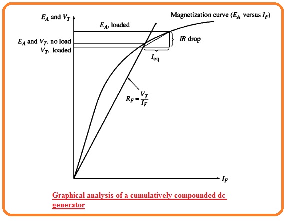
- the terminal voltage for no-load states will be point over the resistance line and the magnetization curve meets.
- When load is linked to the generator the series field MMD rises increasing the equivalent shunt Ieq and resistive voltage losses IA(RA+Rs) in the generator.
- To determine the new output voltage in the generator move the left corner of the resulting triangle with the shunt field current line till the top point of the triangle meets the magnetization curve.
- The upper point of the triangle then denotes the internal generated voltage in a generator while the lower line denotes the VT of a generator.
- The below diagram denotes the procedures repeated numerous times to make a complete terminal characteristic for the generator.

Read also:
- EMF Formula for AC Generator: Parts, Working Mechanism, Phases, and Examples
- Difference between Synchronous Generator and Induction Generator
- Differentially Compounded DC Generator
- Difference Between Alternator & Generator
- Synchronous Generator Transients
Faqs
- A cumulatively compounded DC motor has a series of field winding connected in such configuration that its magnetic field is added to the field of shunt field winding. In a result, a motor with high starting torque is best for projects where high starting loads used
- The cumulatively compound DC generator, series field added the shunt field, and compounding based on series field excitation with an increase in load current
- It is used for operating constant speed line shafts, constant speed head centrifugal pumps, milling machines, grinders, small printing presses, metal cutting machines, etc
- In cumulative compound generators series winding helps the magnetic field generated with shunt winding, and for differential compound generators, series winding hinders the magnetic field produced with shunt winding.
- A compound wound DC generator is a hybrid between series wound and shunt wound motor design. It is also called a cumulative compound motor and comes with combined features of series wound and shunt wound motor high starting torque and efficient speed regulation.
That is a detailed post about Cumulatively Compounded Dc Generator. If you have any further queries ask in the comments Thanks for reading. Have a nice day.