 Hi reader I hope you all are having fun in your life. In this post, we will have a detailed look at Speed Control of Shunt DC Motors. Dc motor belongs to such a category of machines that used dc power for the creation of mechanical power. In different types of industries where the load is dc operated dc motor is used.
In the previous post, we discussed the shunt dc motor with the details. In this, i will explain to you the commonly used method used for speed control of shunt dc motor. So let’s get started with Speed Control of Shunt DC Motors.
Speed Control of Shunt DC Motors
- There are 2 most common methods used for speed control of the shunt motor.
- Field resistance RF adjustment.
- The terminal voltage applied to armature adjustment.
- With these two methods there is one another method used for speed control but it less used.
-
- Connecting resistance in series combination with the armature circuitry.
Let’s discuss these methods one by one in detail.
Changing field resistance
- For learning the effect of field resistance on dc motor variation. Let’s assume that the value of field resistance is rising.
- With the increment, in-field resistance field current reduces according to this formula.
IF=VT/RF
- With the decrement in field current, the value of flux also decrements in direct relation.
- The decrement influx results in an instantaneous decrement in the internally generated voltage value.EA=KΦW. Due to that, there is an increment in the value of armature current.
IA=(VT-EA)/RA
- The induced torque value in motor is given by this expression Tind=KΦIA. As the value of flux in this motor decreases with the increment in armature current.
- To discuss the way with which the value of torque induced varies.
- For this, we solve a practical example.
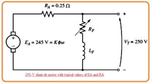
- In the below figure you can see that shunt dc motor having an internal resistance value of 0.25 ohm and its terminal voltage is two fifty volts, While internally generated voltage is two forty five volts.
- Value of armature current is IA=(250V-245)/0.25ohm= 20 Ampere.
- If it is a one percent decrement in the flux of this motor what will results?
- Due to a decrement influx of one percent, internally generated voltage should reduce also one percent. Since EA=KΦW.
- So the value of internally generated voltage will be.
EA2 = 0.99 EA1= 0.99(245 V) = 242.55 V
- The value of armature current will be.
IA=(250 V – 242.55 Volts)/0.25 ohm =29.8A
- So one percent decrement in flux generated a forty-nine peent increment in armature current.
- If we come to our point then we will find that increment in current dominate the decrement in value of flux and value of induced torque increases.
Tind = KΦIA
- Thus torque induced is larger than torque load that caused the increase in speed.
- So with the increment in motor speed internal generated voltage EA increases that cause to decrement in the armature current.
- With the decrement in armature current-induced torque also decreases so torque induced is equal to the torque load value.
- If we do effect and cause involve this technique of speed control or changing speed resistance that some results are mentioned here.
- Increment ins RF causes a decrement in field current IF.
- Due to decrement field current flux also decreases.
- the decrement in flux internal generated voltage decreases.
- reduction of EA increases the armature current.
- Incrment in armarure current resutls in incrmetni in Tind.
- Incemtni in induced torque cause the Tind>Tload and speed also increases.
- Increasing to rises EA = KΦw again.
- An increment in EA reduces IA.
- Decrmenti in armature current causes a reduction in torque induced till torque induced and torque load becomes equal for speed w.
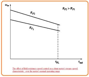
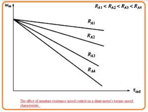
- The effect of increment in FR at the output curve of shunt motor can be seen in below figure.
- Note that with the decrement in flux the speed of the motor without load also increases and the slop of torque-speed is now steep.
Changing Armature Resistance
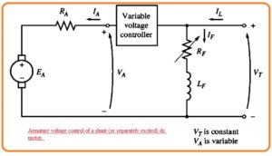
- It is 2nd technique in which varying the voltage given to the armature of the motor without varying the voltage given at the field winding of the motor.
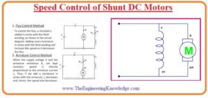
- In this circuit connection shown in the figure should be like this.
- The motor should be in separately excited for armature voltage control.
- If we increase armature voltage VA due to that armature current should also increase.
IA = (VA – EA)IRA
- With the increment in torque induced Tind=KΦIA rises when torque induced is larger than torque load speed motor rises.
- With the increment speed the internal generated voltage EA increases due to that armature current decrease.
- This decrementing in armature current reduces the induced torque which causes tind to become equals the torque load for a large value of speed.
- The key point of this speed control technique are mention here.
- The incrementing in VA increases armature current
- Increment IA rises torque induced.
- Incremntin in induced torque causes for speed increment
- Rise in speed cause to rise in internal generated voltage.
- Due incremnt in internal generaed votlage armatuer current decreaes.
- Decreasing IA decreases Tind until Tind = Toad at a large value of w
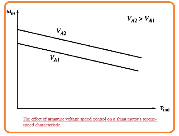
- The effect of incrementing VA at the torque-speed curve for a separately excited motor is can be seen in below figure.
- You can see that no-load motor speed change speed and slop remain constant in this speed control method.
Insertion of Resistance in Series with Armature Winding
- If we connect a resistance with the armature winding in results there is an increment in the slop of torque speed curve of motor but its speed decreases if it linked to the load.
- It is not an effective technique for speed control since there are high power losses about the resistance. Due to this causes it not preferred most.
- it is mostly used in such applications where the motor operates at full speed.
- the most used 2 methods of speed control are field resistance change and armature voltage changes provide safe operation of motor.
- In case of off-field resistance variation technique if less value of field current the motor will move fast and if the field current value is large its speed decreases.
- So the increment in IF results in a decrement in speed so the speed is not maximum through field circuitry control method.
- The least value of speed exists for case when motor field circuitry provides extreme current passing through it.
- If the motor is a function at a terminal voltage that is rated, with that rated power and rated IF so it rotating at full speed which is known as base speed.
- The field resistance method can control a speed that is larger than base speed and not control the speed less than base speed.
- To control speed less than base speed it needs a large value of IF that will burn the field windings.
- While in case of armature voltage control method lesser the parameter voltage value at separately excited dc motor that results in low speed and larger the armature voltage across armature move with high speed.
- Due to rise in armature voltage results in an increment in speed so extreme speed can be obtained through the amateur voltage control method.
- For amature voltage control less value of armature voltage in case of the separately excited dc motor there will be fewer speed and for high armature voltage high speed of the motor.
- So increment in armature voltage results in increment in speed so we can get extreme speed through armature voltage control.
- the maximum value of speed obtained when the value of armature voltage is at a high level.
- If the motor is functioning at rated voltage, rate dIF and rated power than it operating ar base speed.
- Armature voltage can regulate the speed fpr motor speed less than base speed but not for speed large than base speed.
- To get a high speed over the base speed through armature voltage control there will be a need for large armature voltage that will burn armature windings.
- These two methods of speed control are complementary. Armature voltage speed control is good for speed values less than base speed and field resistance method is good for speed values less than base speed.
- If these 2 techniques are used combine then a speed value of forty to one or more can get.
- Shunt and separately excited dc motor provides good features of speed control
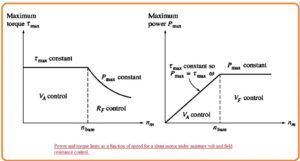
- There is a prominent difference in torque and power restriction at the motor for these 2-speed control methods.
- The limiting factor for these methods is the heating amature condition that put at top limer at the magnitude of armature current IA.
- In the case of armature control, flux in the motor has a constant value, therefore, maximum torque in motor ha a value of.
Tmax= KΦIA.max
- This extreme torque has a constant value irrespective of the speed of rotation of motor. As power coming out of the motor is given as P=Tw the maximum power of motor for any speed in case of armature voltage control is given as.
- Pmax=TmaxW
- So the maximum power taken from motor has a direct relation with the operating speed in case of armature voltage control method.
- While for field resistance control method flux varies.
- In this method speed, the increment is caused the decrement in flux of the machine.
- For limit, the armature current to be exceeded the torque induced limit should reduce with the speed of motor rises.
- As the power of motor and torque restricted reduces with the speed of motor rises the max power taken out from motor in case of current field control is constant but torque changes in reverse order to the speed of motor.
- The shunt dc motor power and torque restrictions for function as of speed can be seen in the below figure.
What is the Effect of an Open Field Circuit
- Above we discussed the speed control through field resistance variation. With the increment in-field resistance speed of the motor rises.
- So here are some factors that come in mind that are.
- What will happen if we increased the field resistance really?
- If we opne the fiekd circitry whne motor is operating?
- According to the above discussion, the flux value of the motor will decrease to Φres and internal generated voltage will also decrease with it.
- It results in the increments in armature current that cause the induced torque to be larger than the load torque at motor.
- So motor speed increases and continues to increase.
- The output of open filed circuitry can be prominent.
So friends that is a detailed post about Speed Control of Shunt DC Motors. If you have any further query ask in the comments. Thanks for reading.


