 Hello, friends welcome to a new post in this post we will have a detailed look at Direction Of Power Flow In Ac System. There is main power system in the ac is the alternating voltage that is delivering to load on regular basis after the generation system. This system consists of three types of main power active, reactive, and apparent.
In this post, we cover the details of power flow and its direction in the system. So let get started
Direction Of Power Flow In Ac System
- To study the basics of power flow direction in the system the main parameters that are taken into consideration are active power, apparent power, and voltage generation and their relation among them.
- Here the main point to be noted is that power is either generated or using through the system by discussing the power flow direction when voltage and current have certain values.
- This point is also applicable to dc systems whether power is generated and used through the system.
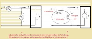
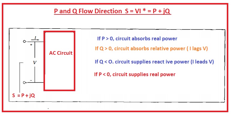
- In below figure, you can see the circuitry where current and voltage are passing
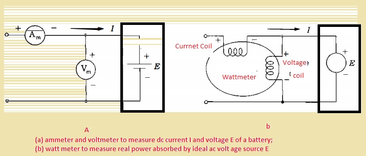
- In circuitry, if the value of Voltage is one hundred volts and the current is ten amperes so the power delivered the battery will be multiple of both current and voltage and its 1000watts
- If now we reverse the connection of the ammeter then results will be the same but with different polarity. -1000Watt is the answer. It means the battey is gettig discahrge
- In figure denoted as b ac system is shown have ideal voltage source that has positive polarity for instantaneous voltage.
- current is flowing in the box for the positive half cycle.
- In figure denoted b there is a wattmeter that has a current coil and voltage coil in circuitry.
- For measures of power both the coils should be attached in proper way to the circuitry
- As the power used by the circuitry is given here.
![]()
- In the above equation θ angle through which the current is lagging volts.
- If there i upscale at the wattmeter according to the connection shown in circuitry denoted above with b the term for the above equation P=VIcosθ has a positive value and real power is used through the system
- If there is a downscale int the meter then P=VIcosθ has a negative value and by changing one connection either current or potential coil we come to see that power having positive value is delivered though the system
- If the wattmeter is connected to the varmeter, these results also work with reactive power.
- Simply, we can find the value of reactive and active power by using the above circuitry. through using the value of polarity for current and voltage according to the below shown
- The value of the real and imaginary portions of the equation S = VI* can be found through the use of power and Q given by the circuitry.
- If the other is currently lagging, the voltage through angle lies between zero and ninety, then P=VIcosθ and P=VIsinθ has a positive value.
FAQs
What is the direction of AC power flow?
- AC changes direction, and we can define that it does not have direction since we can define that it does not have direction since there is not an unvaried direction. We can define that no direction defines no absolute direction. The 2 AC frequencies are 50 Hz or 60 Hz, based on the country.
What is the power flow in an AC system?
- Power flow or load flow in an AC power system works by measuring bus voltage and their phase angle, as well as the flow of active and reactive power through different components in steady-state conditions.
What is the difference between load flow and power flow?
- Load flow generated sinusoidal steady state for completion of system, real and reactive power produced. The load is a static quantity, and it is the power that passes through transmission lines called power flow studies.
How does power flow work?
- Power flow is a conventional power measurement that is done for defining flows on all lines and voltage at uses for system-provided power injections at buses and voltage magnitude at some points.
What is the basic power flow analysis?
- Load flow analysis, called power flow analysis, is a computational process employed for modeling power systems in different working conditions and measuring required features. It lies on Kirchhoff’s circuit laws and is used for defining the steady-state working point of the circuit.