 Hello, friends welcome to onboard. In this post, we will have a detailed look at Introduction to DC Motors. There are numerous machines that are in the power system that are transformer, motor, generator, etc. Each of these machines has it’s own using the most commonly used machines in the electrical system are motor and generator. The motor is such a device that transforms electrical energy into mechanical energy and the generator transformed mechanical power given at its rotor in electrical energy. There are numerous categories of generators and motors according to their power usage and generation process.
The most types of motor and generator is DC motor, ac motor and dc generator, and ac motor. These motors and generators have some further subtypes such as ac motor classified into induction motor, single-phase induction motor, three-phase induction motor, induction generator, synchronous generator, and synchronous motor. In this post, we will discuss the DC motor construction working types and different parts. So let’s get started with Introduction to Induction Motors.
Introduction to DC Motors
- In previous years the power system was used dc power system but in the 1890s the use of ac power system becomes very common to the people.
- But due to the usage of ac system, the importance of dc motor did not end.
- The usage of dc motors was due to numerous causes. One reason is that still currently dc motors are used in vehicles trucks and aircraft.
- With that it still used is there use in such applications where constant speed is not required.
- When there is not commonly used of dc motors were commonly used in speed variation applications.
- At that time there is no existence of a solid-state rectifier and chopper circuitry for the creation of dc power so dc motor was used for offering the required speed regulation.
- Nowadays the induction motor having solid-state drive assembly is used in place of dc motor in speed regulation or control applications. But in some application dc motor are preferred.
- For comparison between dc motors, their speed regulations are compared.
- The value of speed regulation of motor can be found by the given formula.
SR=(wnl-wfl)/wfl x 100%
SR=(nnl-nfl)/nfl x 100%
- This is the rough measure of the shape of torque of motor speed curve the positive value of speed regulation indicates that there is a decrement of motor speed with the increment in the load.
- If the value of regulation negative that means the speed of the motor increases when there is an increment in the load.
- The value of speed regulation explains the steepness of the torque-speed curve.
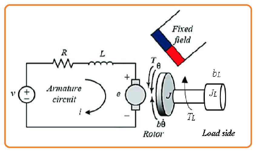
Equivalent Circuit of DC Motor
- The equivalent of DC motor can be seen in the below figure.
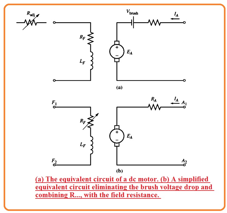
- In this diagram, the armature circuitry is denoted through the ideal voltage source denoted as EA and resistance RA.
- The demonization is the Thevenin equivalent of a complete rotor structure comprised of rotor coles interpolates and compensating windings.
- The value of brush voltage loss is denoted with the small battery Vbrush contrary to the current direction moving in the motor.
- The field coils that generate the magnetic flux in the generator are denoted by the inductor LF and resistance RF.
- The distinct resistance Radj denotes the exterior variable resistance used for controlling the value of current passing in the field circuitry.
- There are some changes to adjustments in this circuitry.
- The value of brush loss voltage is just small fraction of voltage produced in the motor.
- So in a situation where it is not very alarming, the brush loss voltage can be ignored or added in the value of resistance RA.
- With that, the inner resistance of field windings in some cases lumped with the variable resistance and the net is known as RF.
- The 3rd change is that some types of generators consist of more than one field windings that are shown at equivalent circuitry.
- The value of the internally generated voltage of the motor can be find with he below equation.
EA=KΦω
- The value of induced torque in the motor can be given as.
Tind=KΦIA
Magnetization Curve of DC Motor
- The value of internally generated voltage of motor can be found with the below-given equation.
EA=KΦω
- From this equation, we can see that the value of EA in direct relation with the flux passing in the motor and also has a direct relation with the rotation of the motor.
- The value of field current in the dc motor generated mmf or magnetomotive force that is F=NFIF.
- Due to this MMF force flux is generated in the motor according to its magnetization curve shown in the below figure.
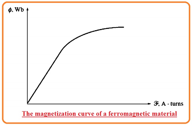
- As the field current is in direct relation to the mmf and EA also has a direct relation to the flux it is compulsory to exist the magnetization curve between EA and field current of given speed w0 shown in the below figure.
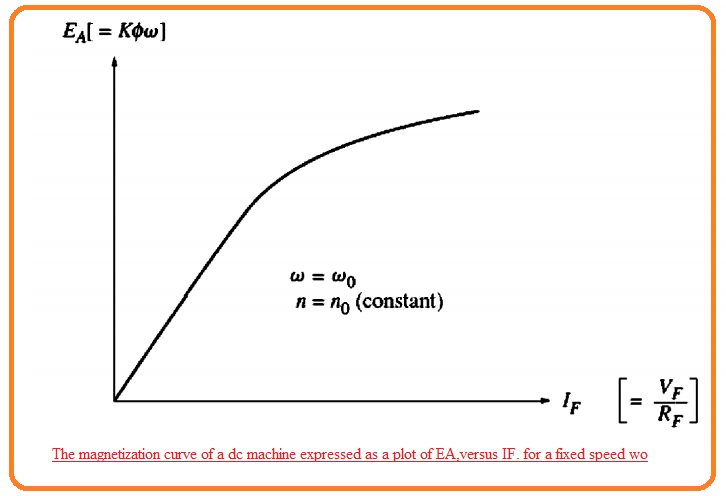
- It is a point to notice that to obtain the large value of power per pound weight of motor their design should be to their saturation point at the ámagnetization curve or at the knee of curve.
- It indicates that a larger increment in the value of field current is almost compulsory to obtain the smaller increment in the EA in case of full load.
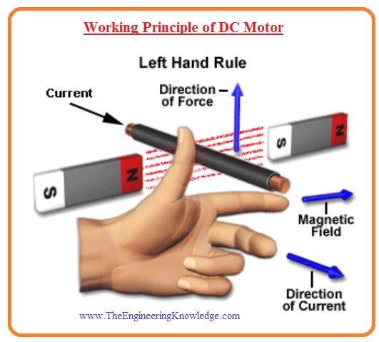
Working Principle of DC Motor
- If the conductor through which current is passing is put int the magnetic field the force or torque exists on that conductor and it moves.
- In simple is that as due to current passing in the conductor field is generated and that field interacts to the other field that causes the production of torque and conductor moves.
- The working operation of the dc motor is according to this rule.
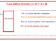
- The rotation direction of dc motor can be found with the use of Fleming left-hand rule that defines that if the index finger middle finger and thumb has such a position that they are at 90 degrees to one another and if index finger denotes the direction of fields and the middle finger denotes the current direction flowing in the conductor then the thumb will denote the direction of the force exerted on the rotor or shaft of dc motor.
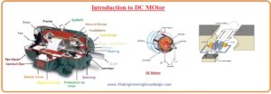
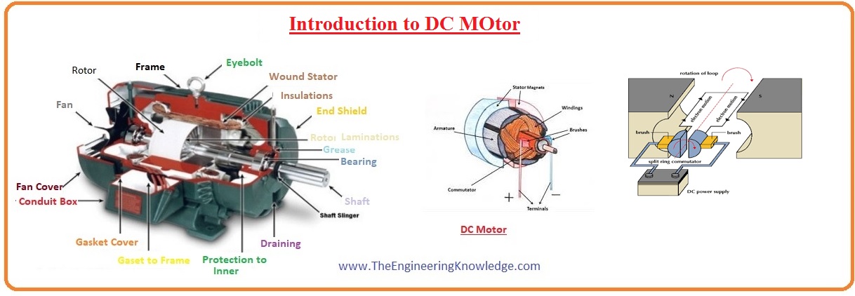
Construction of DC Motor
- The main parts of DC motor are described here.
- Stator
- Rotor
- Yoke
- Poles
- Field windings
- Armature windings
- Commutator
- Brushes
DC Motor Stator
- The stator of dc motor is its stationary part that comprises of field windings and also linked to the input power supply.
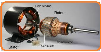
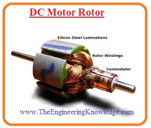
DC Motor Rotor
- It is a rotatory part of the motor that comprises of shaft of the motor through which power is obtained.
DC Motor Yoke
- It also called the magnetic frame of the motor that is created through the cast iron or steel and it is part of the stator.
- The main usage of it is to provide protection to the internal components of the motor and offers to support to armature windings of the machine.
- With that, it provides supports to the fields windings part of motor
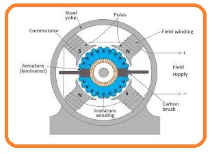
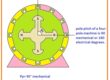
DC Motor Pole
- The pole of dc motor are assembled at the internal part of the yoke. There are 2 main portions of poles.
- The first one is core and pole shoes that are linked to each other through hydraulic pressure.
- There is a different usage of these two structures. The area of pole core is less and its work is to hold the pole shoe on the yoke while the pole shoe has a larger area and used for spreading of flux from stator to the rotor to decrease the losses occurred due to reluctance.
- There is slots that exist on the pole shoe for holding the field windings which generated the flux.
Field Winding of DC Motor
- The field windings of dc Motor are created through the copper wire that wound on the slots of pole shoes in such structure that when field current passes then neighboring poles having reverse polarity is generated.
- The main purpose of field windings is to make an electromagnet that generates field flux in the rotor armature windings of dc motor.
DC Motor Armature Windings
- The armature windings of DC Motor is placed at the rotor that generated the rotating fields that is are in direct cause the production of magnetic losses.
- Due to this cause, the rotor is created to the armature core which is created with such material that has small hysteresis silicon steel lamination for reduction the magnetic losses such as hysteresis and eddy current losses.
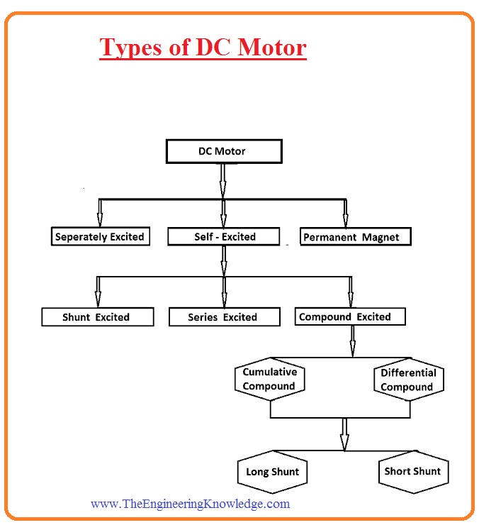
Types of DC Motor
- There are five major types of dc motors.
- I.separately excited dc motor
2. shunt dc motor
3. permanent-magnet dc motor
4. series dc motor
5. compounded dc motor
- I.separately excited dc motor
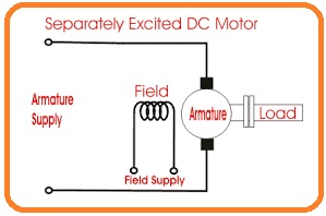
Separately Excited DC motor
- From the name of this motor you can observe that there is a separate supply is required to the field and armature windings for excitation.
- The main fact of this category of the motor is that armature current does not pass through the field windings but instead it field windings need a separate dc source.
- In the below figure you can see the circuit diagram of this motor.
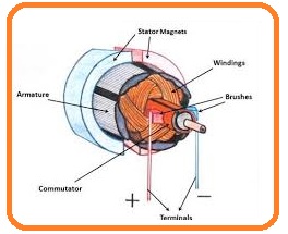
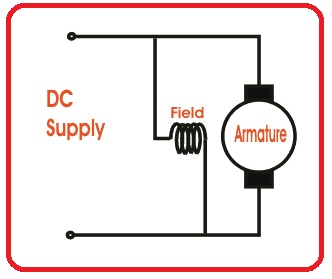
Permanent-Magnet DC Motor
- This motor is also called PMDC and comprises of one armature windings like normal motor but in place of field windings, it uses a permanent magnet.
- These permanent magnets are assembled at the inner surface of the store and it generates flux.
- While the rotor of this motor comprises of armature windings commutator and brushes.
- In below figure you can see the diagram of PMDC.
Self Excited DC Motor
- In this category of the motor, the field windings are linked to the armature windings in series and parallel combination to the armature windings.
- There are three commonly used categories of this motor according to the interlinking of field and armature windings.
- Shunt-wound DC motor
- Compound wound DC motor
- Series wound DC motor
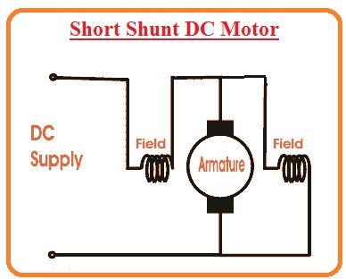
Short Shunt DC Motor
- In this category of motor the field windings and armature windings are linked in such a design that makes a parallel combination so-called shunt dc motor.
- In the below figure you can see the circuit diagram of the shunt dc motor.
So friends that all about dc motor in this post i have covered each and every parameter of dc motor still if you have any further query please ask in the comments. I will try to resolve your queries. Have a nice day.