Hi friends, welcome to a new topic. Here we will learn the EMF formula for AC generators: parts, working mechanism, phases, and examples. The importance of current cannot be denied in any field of life, as this post will discuss the details of EMF generated by AC generators. , charging devices, or industrial machine work based on current. Maybe you think about how electricity is produced, especially in the form of AC? This post will discuss the details of EMF generated by AC generators. So let’s get started with the EMF formula for AC generators:
Introduction to AC Generators
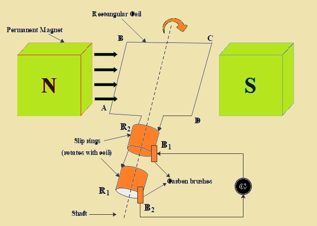
The alternator, or synchronous generator, is called an AC generator or dynamo. It is a device that is used for the conversion of mechanical energy into electrical energy.
Here we will make an EMF equation of the alternator and AC generator.
If magnetizing current is given through a DC shunt generator with two slip rings in the result field, agents move. Most alternators use rotating fields with static armatures.
When the rotor rotates, the stator conductors are static; for the alternator, cut through the magnetic flux, EMF is included through Faraday’s law.
. There are two main AC generators: induction generators and synchronous generators.
AC Generator Components
Stator
The stator is the static part of the generator. It comes with coils of wire that are good for generating EMF. These windings are configured to induce current when a field changes.
Rotor
The rotor is a moving component of the generator. Its work is to produce a changing field that interacts with stator coils. This motion is done through mechanical sources, such as turbine-driven rotation.
Slip Rings and Brushes
The slip rings and brushes component transfers energy from the rotor to the outer circuits. They provide continuous current flow through contacts between the rotating rotor and stator.
EMF Equation of Alternator and AC Generator
EMF Equation of Alternator
Suppose that we have P as a pole and Z as a number of conductors. Z=2T, T is the number of coils.
f is frequency-induced EMF
Φ is flux per pol, N is rotor speed, and Kd is the distribution factor.
Kd = (Sin mB/2)/mSinB/2
Kc or KP = Cos α/2
Kf is a form factor that has a value of 1.11.
For one revolution of the rotor, the flux will be ΦP Webers.
dΦ = ΦP and dΦ = 60/N seconds
As
N = 120f / P
Adding the value of N in equation A we have
EMF for per conductor will be ΦP/6 = x 120f/P = 2fΦ Volt.
For Z conduction in series per phase
If there are Z conductors in series per phase,
average E.M.F. per phase = 2 f Φ Z Volts = 4 f ΦT Volts
Form Factor = RMS Value / Average Value
= RMS value = Form Factor x Average Value
VAV = 1.11 x 4fΦT = 4.44fΦT Volts
The value of the actual voltage of the generator per phase will be as
VPH = 4.44 KC KD f ΦTPH
V = 4.44 Kf KC KD f ΦT Volts
In this equation
- V = generated voltage per phase
- KC = Coil Span Factor
- KD = Distribution Factor
- Kf = Form Factor
- f = frequency
- T = Number of coils
EMF Equation of Synchronous Generator
Let’s suppose P is the number of poles and φ = flux per pole (Webers).
N = rotor speed
Pole flux is ‘φ, so flux in each conductor will be φP. 60/N time taken seconds by pole to complete a revolution.
The average EMF per conductor will be.
EMF per conductor = φP/(60/N) = φNP/60
Where alternator speed, N, will be
f = PN/120 or N = 120f/P
f is frequency, so EMF induced per conductor will be φNP/60 = (φP/60) x (120f/P).
Average EMF per conductor = 2fφ volts
Let Z = No. of conductors per phase, then the emf pretty phase becomes
EMF per phase = 2fφ x Z = 2fφZ
Suppose T is the number of turns, so Z is 2T, and
EMF per phase will be 2fφZ = 2fφ(2T) = 4fφT.
For sinusoidal EMF, the form factor will be kf = 1.11.
The form factor is RMS value/average value.
RMS value = form factor x average value
RMS value per phase = 1.11 x 4fφT
Vrms per phase = 4.44 fφT volts
So, using oil span factor kc and the distribution factor Kd, the actual induced EMF per phase will be
Vrms per phase = Vph = 4.44 kckdfφT volts
Or
Vph = 2.22 kckdfφZ volts
So this equation has
- Vph = induced EMF per phase
- Kc = Coil span factor
- Kd = Distribution factor
- f = Frequency
- φ = Flux per pole (Weber)
- Z = No. of conductors
- T = No. of turns
For a star-connected alternator, the line voltage VL is √3 times the phase voltage.
VL = √3 Vph
Read also
- Difference between Synchronous Generator and Induction Generator
- Difference between Synchronous Motor & Synchronous Generator
- Parallel Operation of Synchronous Generator
- Frequency-Power and Voltage-Reactive Power Characteristics of a Synchronous Generator
- Introduction to Synchronous Generator, Working, Construction, Types & Applications
Faqs
- What is emf in an AC generator?
- An AC generator works on Faraday’s law of electromagnetic induction, which defines that EMF or voltage is produced in current carrying conductors that cut the magnetic field.
- What is the formula for induced emf in an AC generator, Class 12?
- If the coil of N turns and area A is rotated at V revolutions per second in a uniform magnetic field B, then the emotional emf generated is e = NBA(2πv)sin(2πv)t, where t is time zero seconds and the coil is at 90 degrees to the field.
What is the formula for the voltage of an AC generator?
The formula for AC voltage is V(t) = V0 sin (2 pi f t). V0 is called “peak” or “maximum” voltage. In the USA the period T = 1/60 s, so frequency f = 1/T = 60 Hz.
- Where does an AC generator generate an emf E?
- AC generators work on Faraday’s law of electromagnetic induction. If the armature rotates between magnet poles on an axis 90 degrees to the field, the flux linkage of the armature varies continuously. As a result, emf is produced in the armature.
- Does AC produce emf?
- AC power generates electric and magnetic fields that produce a weak electric current.
- What is the frequency of emf in an AC generator?
- The winding of the AC generator rotates at a frequency of 60 Hz and produces an induced emf of 120 volts.
- What is the maximum emf of an AC generator?
- Maximum emf generated in ac is given as ε = NBAω, which has a dependence of emf on the number of turns of the generator’s coil, total area, the magnetic field, and the angular speed of rotation.
- What is the emf equation for a single-phase AC circuit?
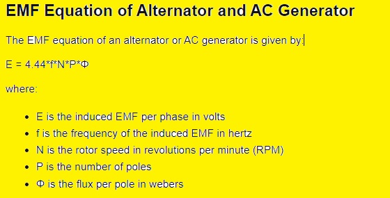
- E = 4.44 Q*f*n here E is in volts, Q is flux in Weber’s, f is frequency in Hertz, and n is the number of turns in primary/secondary. value of flux Q can be = B (flux de ncity in Weber’s per m sq. for steel it is 1.5) * Area of iron in m.
Which is the correct formula for frequency in an AC generator?
Generator Frequency (f) = Number of revolutions per minute of the engine (N) x Number of magnetic poles (P) / 120. f = N*P/120.
What is the formula for a generator?
Generator formula is
emf = 2Bℓvsinθ emf = 2Bℓvsinθ. emf = 2Bℓvsinωtωt emf = 2Bℓvsinωt. emf = 2Bℓw2ωsinωt = (ℓw) Bωsinωt emf = 2 B ℓ w 2 ω sin ω t = ( ℓ w ) B ω si
What is the output of the AC generator?
The output of an AC generator is an alternating current. The alternating current is generated by the rotation of the coil in the magnetic field.
- What is the formula for generator output?
- The AC generator is a machine that transforms mechanical energy into electrical energy. The AC generator input supply is mechanically given through a steam turbine, gas turbine, and combustion engine. Output is AC electrical power in the form of alternating voltage and current.
What is the output of the generator, AC or DC?
- Generator has the feature of AC and DC power. Alternators are made with AC, so it’s called led an alternators. The design difference helps to generator to generate a larger number of watt per kilowatt, which is so substantial.


