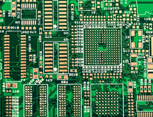
 Hello, readers welcome to the new post. Today we will discuss How to Test Circuit Board with a Multimeter. The full form of PCB is a printed circuit board used to make the connection of electric components to make projects and circuits. It uses conductive layer pads and other parts for PCB assembly. These elements are the configuration of mechanical collaboration to electric modules that are configured on the board through the use of soldering.
All electronic components on the board are configured to make circuits accurately according to users’ demands and requirements. But sometimes faults come or any component is not configured accurately that make incorrect circuits and operations. To finds the faults and incorrect configuration there are different types of test are performed. So we will discuss how can find the flats through the use of a Multimeter. If you are new to the PCB board will need experts to perform the PCB fault analysis test. SO there is only one PCB manufacturer and the PCB expert is PCBWAY. PCBWAY which manufactures the PCB board also offers PCB testing services with good expert engineering so you visit PCB to find any error in your project. PCB offered the different tests that are listed here for PCB board
-
- Visual inspection after SMD Process
- Free AOI Testing
- X-ray Testing for BGA package, Function Testing, etc with extra charges.
- Final visual inspection
- By getting the PCB testing services you can also get the PCB board at good rates
- Normally, PCBs they shipped PCBs within 3-5 days when you pay them, if you have special delivery time requirements, they can offer express delivery service within 24, 48, 72 hours, please feel free to contact them
- ThePCB with dimenions Length<5cm and Width<5cm 10pcs having manufacturing process
- FR4 1.6MM HASL Pb-Lead Green Soldermask,White Silkscreen,Fly-Probe-Testing(Line Width&Space>=0.15&0.15mm Via&Pad >= 0.3&0.6mm) can be get in just $30 dollars
- More than 200 new company customers come to PCBWAY every month. Many come as referrals from satisfied customers. they have now earned the trust of over 20,000 ENGINEERS and 800 CONTRACTOR ASSEMBLERS who depend on PCBWAY for their PCB requirements
- They also have the best online shipping service in the industry they are currently shipping fifty percent of their order early. In fact, they put money where their mouth is . . and they ship Standard Spec orders on time or they’re FREE!
- In March 2021, as a reply to desires by clients for to introduce a CNC / 3D printing service to create the progress of attachments easily, PCBWay started the launch of their 3D printing service with the aim to work as a single solution for each user’s requirements for the developed of new hardware yields. Introduced a rapid prototyping unit that offers the 4 main services CNC Machining, and Sheet Metal Fabrication. Injection Molding, 3D Printing.
What is PCB Board
- The PCB board first time was invented by Paul Eisle in 1936. But was commonly used in 1950 when this new technology was used by the USA military in different instruments and bomb detonators.
- Currently, PCB has become very common in different projects and electronic devices like mobile, computers laptops watches, etc
- It is constructed with the use of fiberglass having different electronic components on the boards to make the circuits.
- It commonly used color is green due ot solder mask coating but can be get in different colors like red, blue green black from the PCBWAY with good rates and quality.
- On September 13, 2021, PCBWAY offered different color combinations for the solder mask, which are pink-gray orange and transparent. Before this addition, they also offer matte black, matte green, and purple to meet the needs of users, now they offer gray pink, and orange masks.
PCBWAY offers these functions for advanced PCBs, not standard PCB functions.
PCBWAY also offers a new black core PCB material which is black FR-4 and will be charged extra.
More details offered by PCBWAY for solder masks can be found here 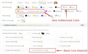
- Copper etching is used for the creation of PCB board trough using the circuit schematic. Different methods are used but the most commonly used is chloride solution.
- If etching is not done a finely short circuit of traces can exist to disturb the circuit.
- In some cases, shorting can be done through not accurate designing of copper plate
- So in the complex circuit, if there is shortening exists is not easy to find so must have experts to solve this issue like PCBWAY since they are equipped with professional engineers as well equipment to find any faults
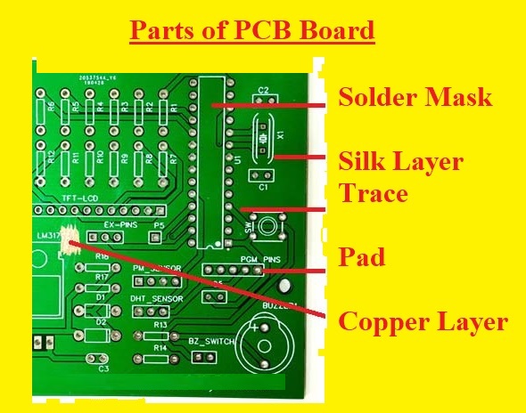
Parts of PCB Board
- The commonly used boards are having copper traces on the surfaces and are known as single-layer boards.
- In a single-layer board, there is outer and internal layers that exist. The main parts of PCB are explained here which will help you to perform the multimeter testing on the board
Substrate
- The substrate is the base of the board that can be created through use of FR4 metallic and ceramic material. All these materials have great features and can work for long timer intervals. Different values of thickness for the base is used.
- Less cost board uses through uses of fewer features of FR4. But from PCBWAY you can get high-quality FR4 material
Copper Layer
- Copper layers consist of copper foil that has limited from the board through heat and adhesive reaction
- It exists for both sides of double layers and on one side of a single layer
- To layer, the board explains that there are 2 layers existing in the structure
Solder Mask
- The PCB color commonly is green due to the solder mask but it can be of other colors. This layer helps to give insulation to the copper traces by preventing them from making contact with the metallic or soldering
Silkscreen
- A white color silkscreen layer is applied to the upper part of the solder mask. where different letters symbolic representations and numbers are written that are used to connect the components
- Silkscreen of any color can be used but most used is black red and yellow
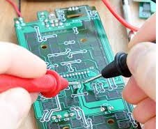
How to Test Circuit Board with Multimeter
- Board testing to find faults is considered a significant parameter. If we do not perform any tests on the board can not get any error existing in the board that will cause problems during circuit operation and board utilization
- To avoid any damage and make our board in accurate working there is a need of testing to complete an accurate function of the board
- During the production of the board, tests make sure that to find the errors, and these error findings at the right time make our projects accurate
- The PCB designer and manufacturer make sure that accurate testing is done to guarantee the products accurate and fine
- Here are some steps discussed to find the error through the use of a multimeter.
- First of all, set your meter and on the unction needle to AC or DC volts setting. The PCB and net volts will be shown at the meter screen.
- After that do the unplugging of the instrument and housing. then on it and make sure that there is no touch of any wires with your hands
- by using the digital multimeter to find the value of volts and resistance. To perform this stage accurately do the basic tests. Press on the problems of meter to find the test points existing on the board
- Finds resistance or volts value. To attach the resistance of the resistor attach one probe with the endpoint of each resistor
- To find that every part is working correctly perform the previous step for each component on the board. It will indicate us to find that all faulty components existing on the board
Conclusion
- The troubleshooting of the board has become very necessary for our projects. With the use of electrical instruments the use of PCB also used increased. So small errors in the board can make a faulty complete circuit. SO digital multimeter can be used to find the fault if not happening easily for you must contact the PCBWAY to find the fault


