 Hello, friends welcome to the new post. In this post, we will discuss Running a Load Flow Analysis ETAP. This tutorial will teach us to load flow analysis and offers the different steps about the running of load flow in the project constructed in the ETAP. Here we will also learn regulation of bust voltage through the use of LTC and ETAP flags overload requirements.
So let’s get started.
Running a Load Flow Analysis ETAP
- To study the laod flow analysis press at the Load flow analysis tab shown in the below figure shown at the mode toolbar.
- Pressing on this button will be the output report. The tab of the study case toolbar will open after pressing at load flow analysis from where we can choose the name of the already created output report to edit it.
- If we choose prompt then running load flow analysis will be a move to the new report name for creation.
- There is lot of option exist in the study to change according to our requirements. For instance, different techniques having large numbers of variations and accuracy can be mentioned load diversity factors can be provided and at last different variations can be chosen for different components such as reactor, overload heater, cable, transformers, etc.
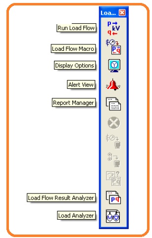
- To get the results from the load flow press at the run load flow button indicated in the load flow bar.
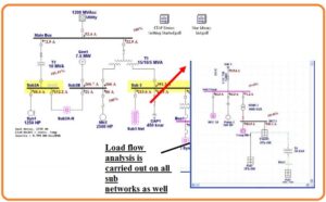
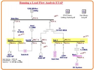
- When we run the load flow analysis the outputs will be shown at the one line can seen here.
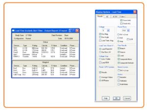
- The outputs seen at the on line and type which care shown can be varied in the display tabs that exist at the load flow bar.
- To study the overload difficulties just press at the alert tab button exists in the load flow bar. It will open display existing at a tab of non-required device.
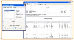
- Results delivered a method to show further data and prepared denotation of the outcomes. Press at the report manager existing at the load flow menu bar and move to the outcomes display and choose laod flow report. Here we can observe different layouts of data to show at the outcomes report.
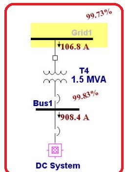
- Observing the outcomes at the one line observe that the operating voltage of first but or BUS1 is 97.89 percent.
- It results in the bus to be flagged according to margins in the under-voltage at the alert view window.
- The rules through which the state of flagged can be varied in the Load flow study case. Here we will work on the usage of bus voltage regulation specification of the transformer editor to make betterment in our load flow outcomes.
- ETAP permits auto LTC variations to be used to vary buses that are in direct or indirect link to the transformer.
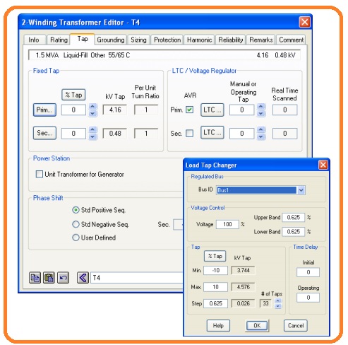
- For instance, we can operate transformer T4 to do regulation at Bus1 at one hundred percent of nominal voltage.
- Opening the editor of T4 through pressing the double pressing at the graphic of one line.
- Pressing the LTC settings display through pressing at the LTC tab and vary the regulated ID to BUS1. Press at Ok for two LTC displays and the transformer editor display.
- Operating the load flow study by giving importance to the working voltage at Bus 1.
- Note that the operating voltage of Bus1 is according to tab adjust by the required one hundred percent regulation parameters.
- Running of the load we can discuss the results of information for different components in a very accurate and comprehensive method through the use of load flow outcomes analyzer shown here.
- Load Flow Result Analyzer


