 Hello, friends welcome to the new post. In this post we will learn How to Draw Single Line Diagram on ETAP. In this post, we will cover how we can make a single line diagram in the ETAP software. In a single-line view, there are numerous components that can be connected to the completion of the complete network in the circuit is discussed.
Here we will discuss the complete detail about the creation of a one-line diagram with the detailed and create a project that will help for the understanding of the one-line diagram.
What is an electrical single-line diagram?
- Before the creation of a single-line, you must have knowledge of it. The single line diagram is the map or blueprint of the electrical power system.
- This line helps to understand the coming power from the system to the load connected to the system also provides the rating and sizes of devices link to the systems.
How to Draw Single Line Diagram on ETAP
- To draw a single line diagram on the ETAP we will discuss all steps one by one.
- For this, you must have an installed ETAP software on your computer.
- Click on the Etap then choose the New Project option.
- Then you will see the ETAP work area where we will make our project.
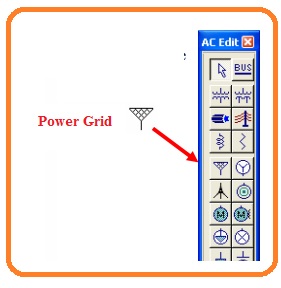
- For the creation of a one-line diagram click at the Edit button that exists at the mode toolbar. As shown here.
- From the AC edit toolbar choose the Power Grid component by pressing at the power Grid tab that is shown in the below figure.
- Then your cursor changes shape to the Power Grid Icon when you take the cursor at the OLV.
- For placement of utility at one-line diagram press at the OLV.
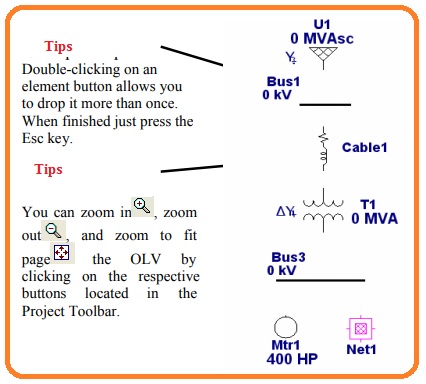
- Through doing the above procedure select the given below components from the AC edit. here are some tips mentioned that will be helpful for you.
- If you need to increase the length of the bus you just have to drag it through either side of the bus. For this double arrow will comes when you has increased the length according to requirements.
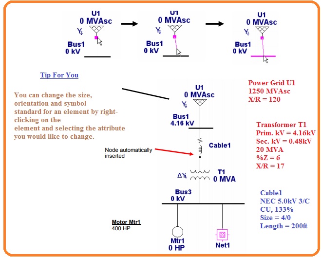
- After selection of components for one line diagram now make the connection between them.
- For this move pointer at the pin for connection of component and its color will become red. After that click on it and move the red color line to the component with which you have to make the connection.
- DO this process with other components for making connections.
- For bus, any part of it can be used as for connection making mean you can connect component at any place.
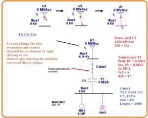
- Here in below figure, you can note that node will automatically come when the cable is linked to the transformer.
- According to the above figure put the values of components through the editing elements properties option.
- Note that the voltage values of buses will change automatically in the primary and secondary Kv of the transformer properties.
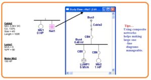
- The creation of an already completed network is like to the new online diagram.
- For opening the composite network you just has to press double at its design. The name of the window shown will be OLV1=>Network1.
- We can vary its name by pressing double at any place in the network OLV or by pressing right at their graphic and choosing the properties.
- For removal of extra components or online look good press right and choose to Hide Unconnected pins.
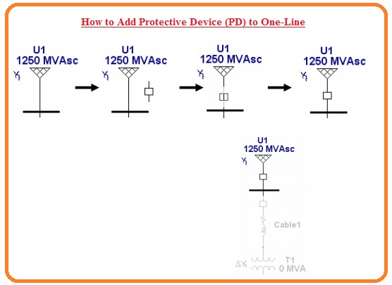
How to Add Protective Device (PD) to One-Line
- We must make sure that there is a certain place among the components we has to put to add a protective device. Connection of PD at the one line not needed to remove the connected components.
- But we can place PD at any point of one line. PD will by its own make a connection to the line.
- Here is some steps are discussed to connect PD to the one line.
- To confirming the component either is energized or not press at the continuity icon placed at the project toolbar.
- All components which are not energized will show a gray color.
- For instance, to check continuity on doing the open circuit for CB4. Here you can see in figure CB4 is gray and all other downstream components.


