 Hello, friends, I hope all of you are enjoying your life. In today’s tutorial, we will have a look at Power Supply Filters and Regulators. In previous tutorials, we discuss half-wave rectifiers and full-wave rectifiers with the detailed. Half wave rectifier is circuitry that transforms positive half of the input signal of AC signal into the DC. The full-wave rectifier converts both halfs positive and negative half into the direct current. We also discussed that the output of these rectifiers is not pure DC and have some fluctuations in output. To remove these fluctuations power supply filters are used. The filter circuit is very important for different electronic circuits and devices as for their operation DC pure DC voltage and current are needed.
In today’s post, we will discuss different types of power filters for the filtration of DC output of rectifier circuits and voltage regulators to maintain the output at a certain level. So let’s get started with the Power Supply Filters and Regulators.
Power Supply Filters and Regulators
- In most power supplies AC voltage having a sixty-hertz frequency is transformed into the dc voltage.
- The output of a half-wave rectifier having a frequency sixty hertz or output of a full-wave rectifier having a frequency of one-twenty hertz should be filtered to remove fluctuations before connecting with the load.
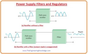
- The below figure shows the use of filters in the rectifier circuit and its result.
- The minor fluctuations in the output of a filter are known as ripple.
Capacitor-Input Filter
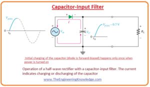
- The half-wave rectifier circuit having a capacitor is shown in the below figure.
- You can see that the filtering circuit is only a capacitor attached to the output of the rectifier and ground terminal.
- The resistance connected with the circuit is equal to the total resistance offered by the load.
- Now, we will discuss the filtering process of a half-wave rectifier and expand it to the full-wave rectifier circuit.
- In the above figure, you can see that the diode is in forward-biased condition of the first quarter part of a positive cycle of input signal.
- During this cycle, diode gets charged to within 0.7 volts of the peak value of the input.
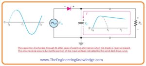
- In the below figure you can see that when the input signal moves to decrement from a peak point during this process diode is becomes reversed biased and a capacitor is still charged.
- Throughout the residual portion of the wave, the capacitor can release charge only over the load resistor (RL) at a rate find by the RLC that is time constant, it longer than the time interval of an input signal.
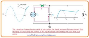
- In the below figure the first quarter portion of next cycle of an input signal is shown. The diode will be in forward biasing condition when the value of input voltage is larger than the voltage stored in the capacitor by the almost 0.7 volts.
Ripple Voltage
- As observed the capacitor charges very fast at the start of the input cycle and gets discharged very slowly after the positive extreme point of input voltage across the load resistance.
- The alteration in voltage of the capacitor after charging and discharging is known as a ripple voltage.
- Ripples are not good for the filtering process so if their value is less then the filtering action will be fine.
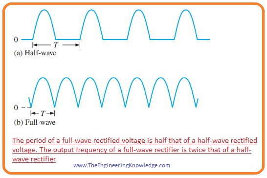
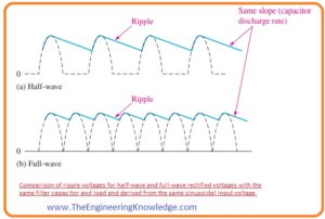
- In below figure you can see that the output frequency of half-wave rectifier is half the output of the full-wave rectifier.
- Due to this high value of frequency, the filtering of a full-wave rectifier is easy due to less time interval among peaks as compared to the half-wave rectifier.
- After the filtration process, the output voltage of a full-wave rectifier has fewer ripples than the output of a full-wave rectifier instead of having a similar load and capacitor connected.
- Due to the short time interval among the output voltage signals of a full-wave rectifier, the capacitor gets less discharged.
Ripple Factor
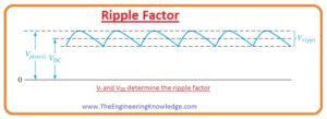
- The ripple factor (r) is a parameter that defines the efficiency of a filter. Its formula is given here.
r= Vr(pp) /VDC
- In this equation, the Vr(pp) is the peak-to-peak ripple voltage and VDC average value or DC value of the output of the filter circuit. It is shown in the below figure.
- If the value of the ripple factor is less then the filtering of the rectified voltage will be fine.
- There are 2 methods to decrease the ripple factor first is to increase the value of capacitance of the capacitor used for filtration and the second method is to increase the resistance of load connected with the circuit.
- The peak to peak ripple voltage and dc value of output voltage of filter VDC in case of a full-wave rectifier circuit are written in the following equations.
- From these equations, you can conclude that if RL and C have some increment or increases then there will be an increment in dc voltage and a decrement in ripple voltage.
Vr(pp) = 1/(fRLC)Vp(rect)
VDC= (1-1/(fRLC))Vp(rect)
Surge Current in Capacitor-Input Filter
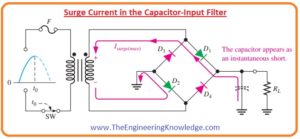
- In the below figure you can see the circuit that has an uncharged capacitor before the closing of a switch of the circuit.
- After the closing of a switch, the voltage will be provided to the bridge circuit the charge less capacitor will behave like a short circuit as shown in above figure.
- Due to it first surge of current produces Isurge through the 2 diode D1 and D2 that are in forward biased condition.
- If the switch is closed at the peak point of secondary voltage due to that maximum surge current Isurge(max) is generated that uses of worst-case condition as also explained in the above equation.
- In the circuit, a fuse is used to limit the initial surge current normally all DC power supplies have a fuse.
- The rating of the fuse is set according to the load connected with the power supply.
- As in the case of the ideal transformer the Pin = Pout so the value of current at primary winding can be found as.
Ipri = (Pin)/120V
- The rating of the fuse must be twenty percent greater than the value of primary current.
Voltage Regulators
- As a filter can decrease the ripples of the output of rectifier circuit the best method to improve the output of rectifier to the desired value is to use a voltage regulator with the capacitor filter circuit.
- The main purpose of a voltage regulator is to maintain the output voltage at a certain level irrespective of the variation in the input voltage due to the current variation of temperature variation.
- The output of the filter provided to the regulator is at an acceptable level. The use of a larger capacitance capacitor and voltage regulator makes the output of very fine.
- The regulators are ICs and have 3 connection points, the first is input, the second is output and the third is a reference point.
- The input of regulators comes from the filter output which has a ripple level of less than ten percent.
- After that, the regulators will decrease the ripple almost to zero.
- Most regulators have some circuits such as interior voltage reference, short circuit protection, and thermal shutdown circuit.
- They exist in different ranges of voltages, containing positive and negative outputs, and can be manufactured for adjustable outputs with the least of exterior elements.
- Usually, voltage regulators can provide a constant output of 1 or more than one ampere with the less ripples.
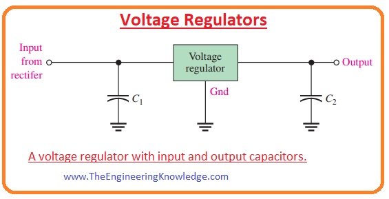
- The regulator has 3 terminals used to get a fixed value of output voltage is shown in the below figure.
- In the above circuit, you can see that there are two capacitors first at the input side of the regulator and second at the output side of the regulator. Normally the capacitance of the output capacitor is 0.1uF to 1.0uF.
- The filtering process done by the input capacitor and output capacitor of the regulator increases the transient response.
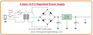
- in below figure the power supply having plus five voltage regulators is shown in the below figure.
So friends that is the complete tutorial about the Power Supply Filters and Regulators. If you have any further queries about this post ask in comments. See you in the next post. Have a good day.
Read also:
- Transformerless 6V DC Power Supply
- 11 Volt Power Supply Circuit using LM7811
- Constant Current DC Power Supply Circuit using LM317
- LM338 Variable Power Supply Circuit
- Introduction to Switch Mode Power Supply (SMPS) Module PCB
- Introduction to Power Supply
Faqs
- As rectifiers generate pulsating DC voltage filters and regulators are used for smoothing the voltage and providing steady value.
- It also defines how the capacitor input filter operates for reducing ripple voltage with charging and discharging between peaks.
- A power filter is an electronic component that reduces electromagnetic interference in the power line of devices. It reduces noise in power flow in the proper way with a quality power noise filter.
- The automatic voltage regulator is an electronic device that keeps a constant voltage level for electrical instruments on the same load. AVR regulates voltages to provide a constant and reliable power supply.
- The main types of filters are high-pass, low-pass, band-pass, and band-reject
- Since capacitor works as simple noise filter through blocking DC current and providing noise to pass. But as there are many types of capacitors with different features, it used in imporper way can end up increasing noise.

