 Hi reader welcomes to another interesting post. in this post, we will have a detailed look at DC Series Motor Working and Applications. With respect to construction or physical dimension, there are 2 basic categories of dc motors first one is self-excited and the second one is a separately excited dc motor. There are further three subtypes of self-excited dc motor which are the Dc shunt motor, dc compound motor, and dc series motor.
In this post, we will cover the detail of the dc series motor, its construction working, operation, application, and related parameters. So let’s get started with Introduction to DC Series Motor.
Introduction to DC Series Motor
- The DC series Motor is such a dc motor that is used in such applications where a high quantity of torque is needed.
- Its construction is such that armature windings and field windings are linked in a series combination. Such configuration helps to generate a large quantity of torque.
- The number of turns required in field windings is less than the turns of windings used in armature windings.

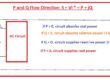
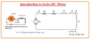
- In the below figure, the equivalent circuit of a series dc motor can be seen. You can see that in this circuit same current passing through the armature windings, and field windings.
- If we apply KVL to this circuit then we have.
VT=EA+IA(RA+RS)
Induced Torque in Series DC Motor
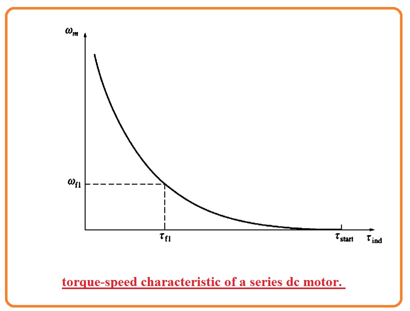
- The terminal characteristics of the series dc motor is like the parameters of the shunt dc motor.
- Its operation is based on that flux has a direct relation with the current flowing through the armature or IA till the point where we get saturation.
- With the increment in the load connected to the motor flux also rises. Due to the increment in flux speed of the motor reduces.
- In a result, the torque-speed curve of the motor is sharply dropping.
- The induced torque for this motor is mentioned here.
Tind=KΦIA
- As the flux for this motor has a direct relation with the IA for the saturation point of material used in the motor rotor. The equation for flux will be.
φ=cIA
- Here C is constant. The equation for the induced torque of this motor will become.
Tind=KΦIA
=KcIA∧2
- From this equation, we can see that torque has a direct relation to the square of the armature. So this motor gives high torque than any other type of motor.
- So it prefers such applications where high torque is required. Like stator motors in cars, elevators, and tractors.
Terminal Characteristics of Series DC Motor
- For discussing the terminal characteristic of this motor we will make assumptions related to the linear magnetization curve and study the effect of saturation in the graph.
- The supposition of the linear magnetization curve indicates that flux in the motor has value.
KcIA∧2
- This equation will help us to make the torque-speed characteristic curve of the series motor.
- According to KVL law we have.
VT=EA+IA(RA+RS)—–A
IA= √Tind/KC
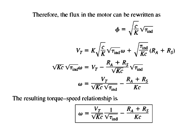
- Putting the value of E=Kw Φ in equation A we have.
VT= KwΦ+√Tind/KC (RA+RS)
- If flux is deleted from the equation so there will be a direct relation between torque and speed of motor.
- Deleting flux from the equation note that.
IA=Φ/C
- We equation for induced torque become.
Tind=K/c Φ2
Construction of Series DC Motor
- The main parts of this motor are armature windings commutator stator field windings and brushes.
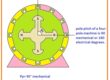
- Its outer part is a stator that is created through the steel and provides cover to the internal parts of the motor. Here in the place of electromagnet poles are also used in some cases.
- The Rotor of this motor comprises of armature windings these windings are linked to the commutators..
- The external power to this motor is given by the carbon brushes than armature windings.
Why Series Motor is Started with No-Load
- The value of the armature current of this motor depends on the load linked to the motor. When there is no load small armature current passes in the motor.
- But if we connect the link large load to the motor when it is starting so motor operates tremendously which causes the damage of motor windings.
Speed control of DC series Motor
- Normally three methods are used for speed control of this motor that are described here.
- Armature resistance control
- Tapped Field control
- Field control
Armature Resistance Control Method
- The circuit for this speed control method can be seen in the below figure.
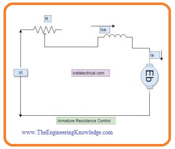
- From this circuitry, you can observe that the change in resistance speed is changed. As there is a series combination between field and armature windings and current flow also the same.
- So current passing in the motor relies on the value of resistance. So if we increase resistance current will decrease.
- The expression for voltage and speed can be seen as.
N ∝ Eb/ɸ
- Speed has an inverse relation to the field current.
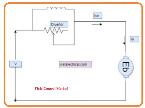
Field Control Method
- The circuit for this method can be seen here.
- In this circuit field, the diverter is linked to the field windings that is in series combination to the armature.
- The usage of this diverter is to help bypass the quantity of armature current in the motor.
- The changes in IA speed of the motor can be varied similar to the above-mentioned method. With the difference that in this current of armature windings, I bypassed through the passing the field windings.
- For this resistance, if linked to the field windings. If the value of resistance offered by the diverted is high current passing in the field windings.
How does a Series DC Motor Work?
The series dc motor transforms electric energy into mechanic energy on the base of the electromagnetic principle. This DC motor power supply terminal is connected to one of the armature and field coils. Through applying voltage, power starts in terminals and passes through armature and field windings.
Conductors in this winding are larger, they come with less resistance. As a result, the motor gets high power from the terminals.
Through this high current in the armature and field coils, a strong field is generated that produces high torque in shafts. This starting torque spins the armature and generates high mechanic energy.
Series DC motor comes with their errors and it is their speed based on load, the heavy load has a lower speed of motor armature and load is less, the speed will increase. So through removing load completely, the motor will work fastly the armature can be damaged.
Why Series Motor is Started with No-Load
The DC series motor must be started with a load since at no load it rotates at high speed.
When a motor is connected to the supply without load, it gets less curent from the supply mains.
That current passes through a series field and armature, speed will increase so back emf can reach to applied voltage value.
The increment in back emf reduces armature current and is called field current.
That causes an increase in speed and back emf. That field continuously decreases and speed continous to increase until the armature generates a centrifugal force that comes out from its shaft and gets damaged.
Read also:
- What is a Shaded Pole Motor : Construction, Working & Its Applications
- What is Circle Diagram of Induction Motor – Definition, Construction & Its Parts
- Introduction to L298N Motor Driver
- DC Motor Control in Proteus using IC L293D
- Advantage of Stepper Motor
Faqs
- Starting shunt motor for high load needed high starting current. To avoid a high starting current, shunt motors not start at high loads and must start without a load
- The construction of dc motor comes with a stator, and rotor part that rotates carry winding. If dc voltage is connected with winding, current flows through it and produces emf
- The series motor comes with high starting torque and is used for starting high inertia loads, like trains, elevators, or hoists. Speed features are good for applications like dragline excavators, where the digging tool moves fast when unloaded but slowly for heavy loads.
- The machine that transforms direct current in mechncal work is called a dc motor. DC motor operated on “Faraday’s law of electromagnetic induction“. Faraday’s law of electromagnetic induction defines that ” if a current-carrying conductor is placed in a magnetic field, it bear force”
- The AC motor uses AC to transform electrical energy into mechanical energy. There are different types of AC motors, DC motor uses dc currents to transform electrical energy into mechanical energy. The main benefit of using this is that helps to control speed and has less coverage area.
- The motor uses the phenomena of the magnetic force on the current-carrying conductor. The direction of force is based on current flow and magnetic field. But we can fix the magnetic field and produce torque on a loop based on current flow. So electric motor made.
What is an application for a DC motor?
- Automotive Industries.
- Hoists & Cranes operations.
- Industrial tools power supply.
- Lifts.
- Air compressor.
- Winching system.
- Elevators.
- Electric traction.
| Motor | Application |
|---|---|
| DC series motor | Traction system, Cranes, air compressors |
| DC shunt motor | Lathe Machines, Conveyors, Weaving Machines, Centrifugal Pumps, Blowers, Spinning machines |
| DC compounded motor | Presses, Rolling Mills Shears, Elevators, |
| Stepper motor | 3D printing equipment,, CNC milling machines Small robotics |
- The benefits of a dc series motor are a starting torque with a high speed of about 500 percent, and a maximum momentary operating torque is about 400 percent. and speed regulation is variable and high for no-load
- Different methods of starting dc series motors exist like two-point starters. The simple starter used for small series dc motor. it comes with two contact points, one for supply and the other common to field and armature coils. The manual levels is engaged to start the motor directly.
What is the construction of DC series motor?
- The components of the motor are the rotor, commutator, stator axle, field winding, and brushes.
- The fixed component of the motor is the stator and made with two electromagnet pole parts.
- Main applications are, rolling mills elevators, steel mills, locomotives, and excavators. For other rotating machines, DC motors result of the interaction of two magnets.
- DC motor is an electrical machine that transforms electrical energy into mechanical. The main working of a DC motor is that when the current carrying conductor put in the field bears mechanical force
- DC motors are devices that transform electrical energy into mechanical energy. DC generator converts mechanical energy into electrical energy.
- The DC motor uses a static set of agents in the stator and coil of wire with curent operating through it produces a field aligned with the center of the coil. One or more windings of insulated wire are wounded about the core of the motor for concentrating magnetic field.
So that is a detailed post about the series DC motor if you have any further queries ask in the comments. Thanks for reading. Have a nice day.