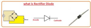
Hello, readers, welcome to the new post. In this post, we will discuss what a rectifier is. The rectifier diode is important for electronics work as the main component of the power supply circuit. These diodes are important for AC to DC conversion. These diodes are used in chargers, power supplies, etc. The diode has two pins: one is a cathode, and the second one is a positive terminal, the anode. So let’s get started with a diode rectifier.
Introduction to Rectifier Diodes
- The rectifier diode, called the rectifier, stops the flow of current in the reverse direction and allows it to flow in a single direction.
- This is a simple component used for AC to DC power. They are commonly used in different electronics projects.
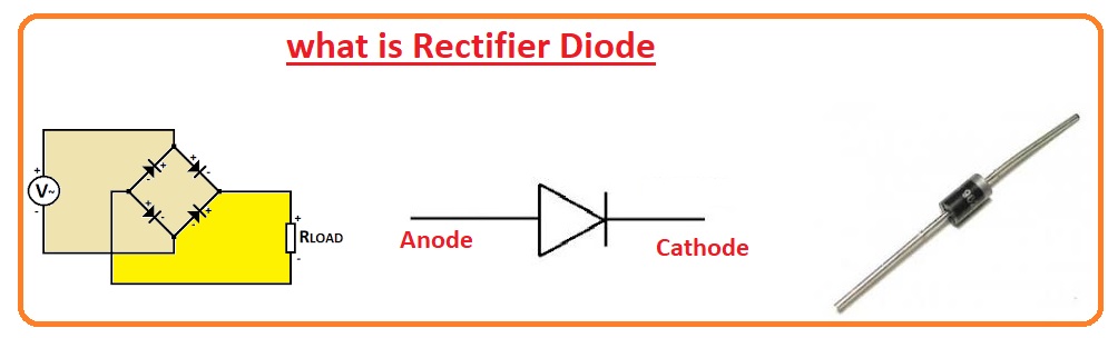
- The symbolic representation of the rectifier diode is lined with an arrow, displaying the current flowing from the anode to the cathode.
- The rectifier uses silicon and, in some conditions, is made with arsenide or germanium.
- There are different types of these diodes, such as silicon rectifiers and Schottky diodes.
Working Principle of Rectifier Diode
- The working of a rectifier diode is a simple process, and the main purpose of the diode is to convert AC into DC in a single direction and stop current flow in the reverse direction.
- For the rectifier diode, the working input AC supply is connected, which gives AC voltage to the diode.
- The diode performs half-wave rectification for half a cycle of AC, helping current to flow from anode to cathode, blocking the negative cycle in the reverse direction.
- The output we get is pulsing DC voltage. This output has only a positive part of the input signal. The DC volt magnitude is based on losses and AC input value.
- The filter circuit is connected for stable DC voltage; a capacitor is used as a filter. The capacitor stores charge when the diode works, minimizing the DC output ripples.
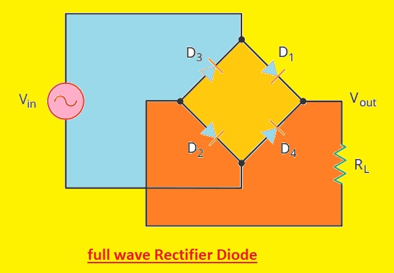
- For getting both cycles of the input signal, the bridge circuit is connected with a 4-diode arrangement. That rectifies both halves of the AC signal and provides constant DC output.
Types of Rectifier Diodes
- There are three types of rectifiers.
- Half-Wave Rectifier
- Full Wave Rectifier
- Bridge Rectifier
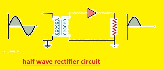
1. Half-wave Rectifier Diode
- It is a simple type of half-wave rectifier circuit.
- The half-wave rectifier transforms AC voltage into DC voltage with the use of a single diode. It just converts the positive or negative half of the signal and provides a single-direction current flow AC to DC.
- It is a less efficient process that has about forty percent of the results of a full-wave rectifier.
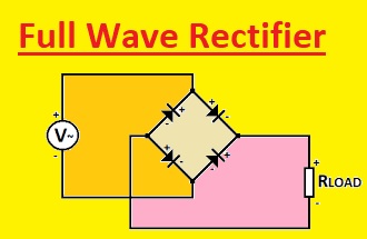
2. Full-wave Rectifier Diode
- The full-wave rectifier diode consists of four diodes and converts the complete AC wave to DC.
- The full-wave rectifier is used in two configurations: the first one is a center-tapped transformer and a 2-diode combination known as a center-tapped full-wave rectifier, and the circuit has four diodes called the bridge configuration, called a bridge rectifier.
- In a half-wave rectifier, only one-half of the AC input is converted into DC, but a full-wave rectifier converts the complete wave into DC.
Bridge Rectifier Diode
- The bridge rectifier diode circuit comes with four diodes and makes a bridge-like design. A bridge rectifier transforms complete AC voltage into DC voltage and the output is DC volts.
How does a rectifier diode convert AC to DC?
Symbol of Rectifier Diode
- The symbol of the rectifier diode consists of the arrow that directs the direction of the current flow. The arrow normally lies at the anode side.
What are the applications of rectifier diodes?
- A rectifier diode is used for the rectification process of AC to DC conversion.
- It is also used for clamping circuits and was used as a level shifter or restoring DC.
- It is also used for the creation of logic gates in digital operations.
- It is also used in the voltage multiplier.
- It is used to protect solar panels and other diodes.
- This diode performs the detection and mixing of signals.
- It is also used in LASER.
- It is also used in ventilation, heating, and AC conditioning systems for controlling the rectification of AC power in the control circuit.
- They are also used in transformers, such as in power distribution systems, for the conversion of AC to DC voltage.
- In CRT monitors and TVs, it is used for converting AC voltage to DC voltage for the electron gun and display operation.
Advantages of Rectifier Diodes
- A rectifier is used in power supplies, DC motors, and other electronic circuits.
- It is an effective and cost-effective solution for the conversion of AC to DC voltage.
- It has features to handle AC and DC input voltage and rectify both positive and negative voltages.
Disadvantages of Rectifier Diodes
- DC saturation of transformer core resulting in magnetizing current and physical phenomenon losses and generation of harmonics. The feature output and rectification potency are low.
Which Rectifier is Used Most?
- Silicon diodes are commonly used in rectifiers for low voltage and power and are mostly used as a replacement for rectifiers.
- The low forward voltage germanium diodes have the advantage of silicon diodes in low-voltage circuits.
What Does the Diode Rectifier Symbol Do?
- The symbol for the rectifier diode is a line having an arrow, showing the current flow from the anode to the cathode. It is best to handle different voltage levels and different electrical power from low to high value.
Ratings of a Rectifier Diode
Peak inverse voltage (PIV):
- Peak inverse voltage is the highest voltage of the diode that can handle reverse-biased direction before breakdown. It is also called the reverse breakdown voltage.
Surge current (IFSM):
- The surge current rating is the maximum non-repetitive surge current that the device can handle. This rating is defined in the form of surge cycles with resulting surge current peaks.
Forward voltage drop (Vf):
- Forward voltage loss of the diode occurs in forward conduction. Silicon diode has 0.6 volts.
Average forward current:
- The maximum forward current that the diode can handle for an indefinite duration. If the average current is higher than this value, the diode will get overheated and can be damaged.
Junction temperature (Tj):
- It is the temperature of the chip in the package. The temperature around the package is called
Ta: Ambient Temperature. Tc (top):
- Temperature of the Top Surface.
Reverse recovery time (trr):
- When the voltage across the diode is reversed, the initial current flow will occur in the reverse direction. Reverse recovery time is taken to stop conduction when the diode is reverse biased.
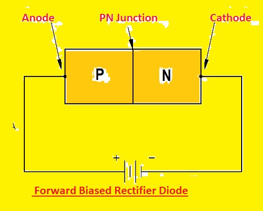
Forward Biased Rectifier Diode
- Diode conduct due to biasing. If the positive terminal of the battery is connected with the P side of the diode, or anode, and the negative terminal of the battery with the N side of the diode, it is called forward bias.
- When a positive supply is given to the P side and a negative to the N side, the majority of carriers repel each other since the polarity of voltage and charge on the majority carrier is the same. That causes drift flow.
- When the electron N side is drifted, it causes the drift current. So in N-type, current is due to electrons, and P-type is due to holes. Drift current due to drifting of majority carriers
- This current is called forward current, and the direction is from positive to negative terminal and reverses the opposite direction of electron flow.
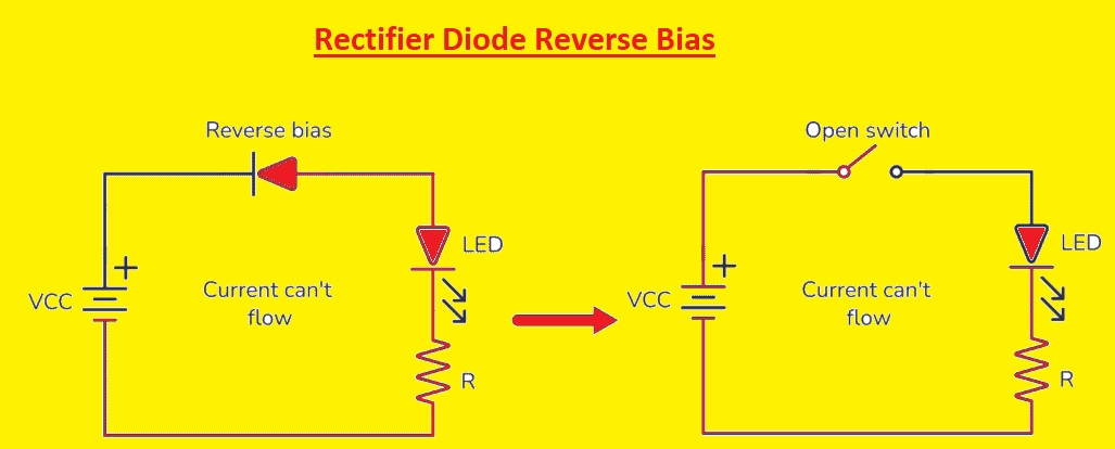
Reverse Biased Diode
- Reverse bias is a standoff configuration; the anode is negatively connected, and the cathode is positively connected with the supply. It makes a strong barrier, thickens the depletion layer, and enhances diode resistance. As a result, less current flow makes a guard-like effect that prevents charger carriers to crossing until the balance is obtained. Forward bias comes, and reverse biases resist it and provide strong protection, protecting voltage balance.
Why is a rectifier called a diode?
What are the popular rectifier diodes?
- Some rectifier diodes are explained here.
Diode Maximum Voltage Maximum Current Maximum Frequency1N4001 50V 1A 1MHz 1N4002 100V 1A 1MHz 1N4003 200V 1A 1MHz 1N4004 400V 1A 1MHz 1N4005 600V 1A 1MHz 1N4006 800V 1A 1MHz 1N4007 1000V 1A 1MHz 1N5400 50V 3A 100kHz 1N5401 100V 3A 100kHz 1N5402 200V 3A 100kHz 1N5404 400V 3A 100kHz 1N5406 600V 3A 100kHz 1N5408 1000V 3A 100kHz 1N5820 20V 3A 1MHz 1N5821 30V 3A 1MHz 1N5822 40V 3A 1MHz 1N5824 60V 3A 1MHz 1N5825 80V 3A 1MHz 1N5829 120V 3A 1 MHz
How to Test a Rectifier Diode?
We use a digital multimeter for testing the rectifier diode. Here the process is explained.
Tools Needed
- Digital Multimeter (DMM)
- A pair of test leads
Procedure:
- First of all, remove power for protection purposes.
- Set the meter to diode mode and check the datasheet for bands on discrete diodes.
- Make a connection of the black lead with the cathode and the red with the anode.
- For forward-biased voltage loss, it will be for silicon 0.5-0.7V.
- In reverse bias, OL is high resistance.
- Verification of reverse bias is continuous beeping, which means the diode is affected.
- Check the polarity and diode behavior. It passes all tests; it can be good. If not, then replace the diode.
What is the difference between a diode and a rectifier?
- The diode is an electronic component that helps the current to flow in a single direction. It has two terminals and a semiconductor device. The rectifier is a device used for the conversion of AC to DC voltage. The diode is used as a switch, and the rectifier is used for conversion.
What is the difference between half-wave and full-wave rectifiers?
How to Use a Rectifier Diode
The rectifier diode moves current in one direction from anode to cathode, called forward bias. The rectifier diode in the forward biasing state is made through the connection of the anode with the positive terminal and the cathode with the negative side.
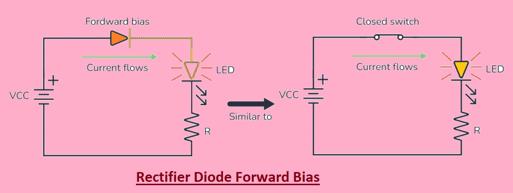
In the above circuit, the diode is forward biased, which means the current flows in this circuit, and the LED connected will glow up. In this configuration, the diode works as a closed switch.
Here the diode is connected in a reverse-biased state where the anode is connected to the negative terminal of the battery and the cathode to the positive terminal of the battery. Here there is no current flow, and the diode works as an open switch.
Related Posts
Difference between normal Rectifier Diode and Schottky diode
Introduction to FR102 Diode Pinout, Datasheet, Applications, Uses Features
Forward biased p-n junction diode
Introduction to 1N4004 Diode & Pinout
Types of Diode and Applications
FAQs
Write the Purpose of a Rectifier Diode.
The main use of a rectifier is to convert AC current into to DC. The rectifier has diodes for this operation. There are many rectifiers: half-wave, full-wave, and full-wave bridges.
What is the symbol of a rectifier diode?
The symbol of the rectifier diode is a line having an arrow, which shows the current flow from the anode to the cathode, used in circuits.
What are the types of rectifier diodes?
- Bridge rectifier
- Rectifier
- Full-wave rectifier
- Half-wave rectifier
- Rectifier circuit phases
- Schottky diodes
- Center-tapped rectifier
- Negative half cycle
What are the advantages of rectifier diodes?
The rectifier is used in power supplies, DC motor controllers, and other types of electronic circuits. It is an effective, reliable, and low-cost solution for the conversion of AC into DC voltage.
What are the types of rectifiers?
Uncontrolled Rectifier and Controlled Rectifier
What is a half-wave rectifier?
The half-wave rectifier transforms AC single to DC by passing the negative or positive half of the waveform and blocking the reverse. Half-wave rectifiers can be made with the use of a single diode and are less effective than full-wave rectifiers.
Half-wave rectifiers are used as mosquito repellents.
In the mosquito repellent, half-wave rectifiers are used to make fumes out of the lead. They provide the signal demodulation.
Where are rectifier diodes used?
They are used in power rectification, like AC voltage into DC voltage.
Can a Zener be used as a rectifier?
Which device is used as a rectifier diode?
What is the function of a rectifying diode?
The rectifier is a certain type of diode that transforms AC into direct current. In this process, AC can reverse direction after some time, and DC flows in one direction.
How does a rectifier diode convert AC to DC?
The diode helps the current move in one direction, making it best for converting from AC to DC. For this, a bridge circuit is used that converts both halves of AC into DC current.
What is an example of a rectifier diode?
A common example of a rectifier is the use of mobile phone chargers. The phone charge can only be charged effectively if a constant, uninterrupted voltage supply is given. It can be done with the use of a rectifier in the phone charger circuit.