
Hello, fellows, I hope all of you are having fun in your life. In today’s tutorial, we will discuss commutation in a four-loop DC machine. The voltage generated at the output terminals of DC machines is pure AC voltage. To convert these voltages into DC voltage, commutators are introduced at the terminals that convert the AC voltages into DC voltages. This process of AC to DC is known as commutation. To a simple understanding of voltage-induced DC machines, you read a simple loop in the field; it will clear your concepts of how AC voltage is induced in DC machines.
In today’s post, we will have a detailed look at how AC voltage is converted to DC by using commutators and some other related parameters. So let’s get started with commutation in a four-loop DC machine.
Commutation in Four Loop DC Machine
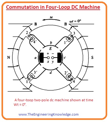
- For a simple study of commutation in DC machines, we take a dc machine that has 4 winding loops and 2 poles, as shown in the given figure.
These winding loops are wound at the rotor in the slots; the rotor is constructed by the steel.
The stator poles are arched to provide identical flux in the machine and a uniform air gap.
In the above figure, you can see that the 4 winding loops are arranged at the rotor in a special technique.
The primed end of every winding loop is the inner end of the wire, and the unprimed end of every winding loop is the outer end of the wire.
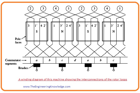
The linking of windings with the commutator is shown in a given figure.
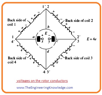
- You can see that the first winding loop is linked with the commutator segments a and b and the second winding loop is joined with the commutator points b and c.
- In the figure given below, you can see that these winding loops (1, 2, 3’) and 4’are under the effect of the south pole. The value of voltages at these winding loops are given as.
eind = (v x B) • I
eind = VBl positive out of page
- The other ends of the windings (1’ 2′, 3, 4) that are under the effect of the north pole have a voltage value as.
eind = (v x B) • I
eind = VBl positive into page
- The complete outcome is represented by the figure given below figure ) every conductor is recognized as one side of the winding loop.
- If the voltage produced at every conductor of the winding coil is (vBl) then the net value of the voltage at the output terminals of the dc machine is given as.
- E= 4e, at wt=0
- You can see that there are 2 parallel paths for current in a machine. The availability of 2 or more parallel paths is the general outcome of the commutation process.
- Here, one question arises.
- What is the effect of the rotor’s continuous rotation of output voltages E?
- The given figure shows the machine at the time (wt=450).
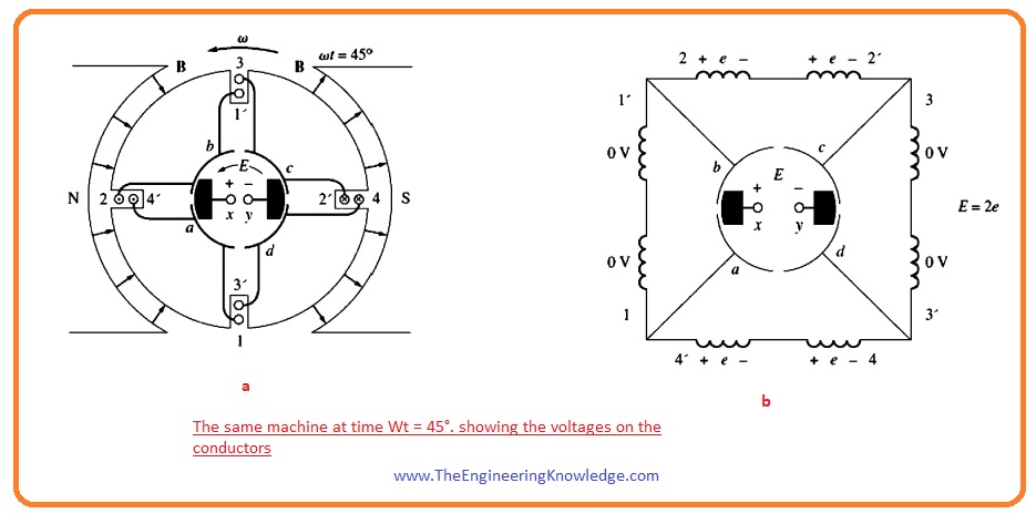
- At this time, the first and third winding loops are rotating in the gap between the poles; consequently, the value of voltage is 0.
- You can see that during this time the brushes are connected with the commutator segments ab and cd.
- It occurs when the voltage at the windings is zero volts, so it creates no problem (connection of commutator segments).
- The second and fourth winding loops are in effect of poles si the output voltage will be.
E=2e, wt=00
- Let’s suppose that the rotor moves for another 450. This condition is shown in the picture given below.
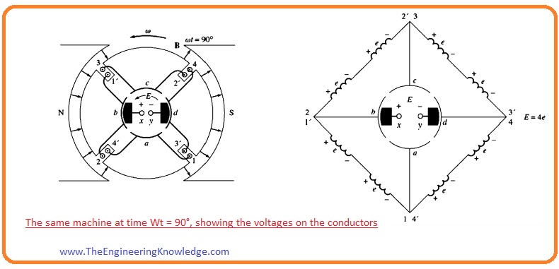
In this case, the (1′, 2, 3, 4′) ends of the windings are an effect of the N pole, and (1, 2’, 3’, 4) are facing the S pole.
In this situation, the voltage produced for the loop’s ends below the N pole is out of the page, and for the other end it is into a page.
Now the 4 current-carrying ends are in every parallel path; thus, the output voltage will be.
E = 4e, wt = 900
If we compare these 2 given figures (A) and (B), the voltage on the first and third winding loops has inverted between the two circuits, and their joining points are also altered, but the voltage production is still similar to earlier.
It is the very important parameter of each commutation arrangement; when the voltage reverses in a winding loop, the connections of the loop are also changed, but the net voltage is still produced in the original direction.
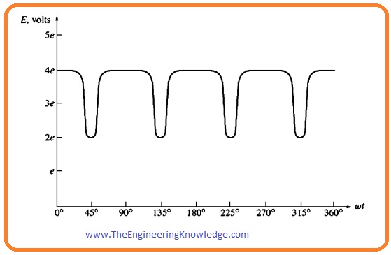
The output voltage of the machine is shown in this given figure.
Summary
- Commutation is the procedure of swapping the loop connections on the rotor of a direct current machine like the voltage in the loop shifts polarity, to provide constant dc voltage at output terminals.
That is a complete post on Commutation in Four Loop DC machine. If you have any questions about this tutorial ask in the comments. See you in the next tutorial.

Hi, I do believe this is a great website. I stumbledupon it 😉 I’m
going to come back yet again since i have book marked it.
Money and freedom is the greatest way to change, may you be rich and continue to help others.
I am struggling to achieve commutation in a 4 pole, 2 brush DC motor.
Field V are 100/200 Arm V are 180
A1 & A2 should just dictate the polarity of the armature.
There are 4 F leads, which I have connected as F1&F3, F2&F4 and also F1, F2&F3, F4.
When we apply 100V to whichever connection as mentioned above on the field system and then try to excite the armature, it’s as if something internally is fighting as the armature tries to spin, but skips and then repeats without ever fully exciting, regardless of the voltage that is applied.
Any suggestions?