 Hello, fellows, I hope all of you are having fun in your life. In today’s tutorial, we will discuss the Simple Rotating Loop between Curved Pole Faces. There are two main types of dc machines first is dc motor and second is a dc generator that produces electrical power through mechanical energy and the motor generates mechanical power by electrical power. Due to their complex structure and complicated windings designing their working and internal structure is not easy to understand.
As in the previous tutorial, we discuss a simple loop in a magnetic field for the understanding of ac machines like an induction motor, induction generator, synchronous motor, and synchronous generator, similarly, for the complication in the dc machines we will also understand by rotating a loop in field of a magnet. In today’s post, we will discuss how voltage is induced in dc machines and torque is induced, by comparison with the loop in a field. So let’s get started with A Simple Rotating Loop between Curved Pole Faces.
Simple Rotating Loop between Curved Pole Faces
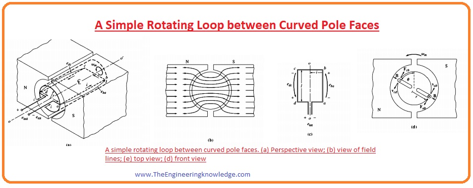
- In the given figure you can see that the simple loop is representing the internal structure of dc machines is rotating in a field around a fixed axis.
- As we knew that in any electrical machine, the static portion is known as a stator and the rotating part is known as a rotor.
- In this figure, you can see that the field is from the north pole of the magnet and end at the south of the magnet.
- You can compare this loop to a rotor that is rotating in the field of the stator which is a magnet in this case.
- We can observe that as the magnet poles are curved in shape so there is the same width of the air gap between the stator (poles) and rotor (loop).
- One main point is that the reluctance offered by the air is larger than the reluctance by the iron of the machine.
- The reluctance faces by the flux to reach the rotor is minimized by following a less reluctance path moving through the stator to the rotor.
- As the flux flows the less reluctance path to reaches the rotor, so it remains at ninety degrees from the stator to the rotor.
- Due to the uniform air gap now the reluctance have the same value from the magnet poles to the rotor.
- This uniform behavior of reluctance tells that the flux is also constant throughout the path.
Voltage Induced in a Rotating Loop
- Now we find the voltage induced in the rotating loop and compare it will with the dc machines.
- As the loop rotors in the field then according to faraday’s law voltage will be induced in this loop, for the understanding of voltage production we discuss the given figure.

- As you can see that the rectangle shape wire loop is in a magnetic field, having the sides ab and cd at ninety degrees to the plane of the page and sides, bc, and da are parallel to the surface of the page.
- The field of magnetic poles or stators is uniform and ninety degrees to the rotor at every point.
- To find the total voltage induced in the loop we will find the value of the voltage at every side of the loop and sum it at the end and use this formula for voltage calculations.
eind = (v x B) • I
Side ab:
- On this side the speed of the loop is tangent to the rotation path. The field is uniform and at ninety degrees to the rotor from the stator at every point of the rotor.
- The speed of rotation V is at ninety degrees to field B, their cross product V x B is into a page. So the voltage produced at the side ab will be given as.
eab = (v x B) • I
=VBl under the pole face
=0 beyond the pole edges
side bc
- At this side, the cross product of field and speed is V x B is into or out of the page but the length of the loop is parallel to the plane, so the terms V x B and length l is at ninety degrees to one another. So the voltage at this side will be 0.
Side cd:
- At this side the rotation speed of the loop is tangent to the rotation track, the field is uniform at the surface of the rotor (loop) and 0 at the endpoints of the loop.
- The speed of rotations I at ninety degrees to the field so the term V x B is out of the page. The value of the induced voltage at this side will be.
ecd = (v x B) • I
=VBl under the pole face
=0 beyond the pole edges
Side da:
- As this side is parallel to the side bc, so V x B is at ninety degrees to length so in this side voltage is also zero.
eda = 0
- the net voltage induced in the loop will be given as.
etot= eab + ebc + ecd + eda
eind=2VBl under the pole faces ——-(A)
=0 beyond the pole edges
- If we rotate the loop at and angle of one eighty degrees then eh side ab will face the north pole of a magnet than the south.
- So the voltage-induced direction, in this case, will be the opposite but the magnitude of the voltage will remain the same. The given figure explains this process.
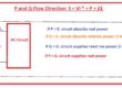
- There is another way to explain the (A) that will compare the working phenomena of the simple loop with the practical dc machines.
- For this, we study the given figure velocity that is tangent is mentioned as.
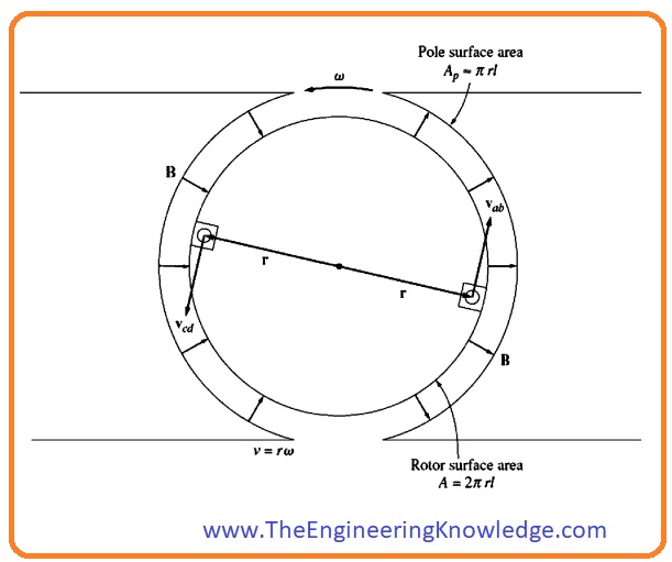
v = rw
- In this equation, the ‘r’ is the radius of the loop from the axis of rotation the edge of the loop and ‘w’ is the angular velocity.
- If we put this V=rw in equation A then we have.
eind = 2rwBl under the pole faces
=0 beyond the pole edges
eind = 2rlBW under the pole faces
= beyond the pole edges
- You can also observe that the rotor is cylindrical, so the area of rotor is 2π As there are 2 magnetic poles so an area of rotor below one pole will be (Ap= πrl)
eind= (2/π)ApBw under the pole faces
eind=0 beyond the pole edges
- As the flux B is the same in this machine, so the net flux under every pole is only the multiple of pole’s area with the flux density.
- So the final equation of voltage induced will be.
eind = (2/π)øw under the pole faces
= 0 beyond the pole edges
- From this equation, we concluded that the voltage induced in dc machines is the multiple of the flux and revolving speed of the machine and product with the constant.
- In simple words, we can say that the voltage induced in any dc machine depends on these three parameters.
- A flux of the machine.
- Rotation
- A constant that represents the manufacturing of the machine.
How to Get DC Voltage out of the Rotating Loop
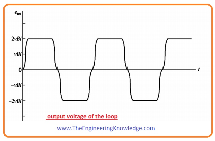
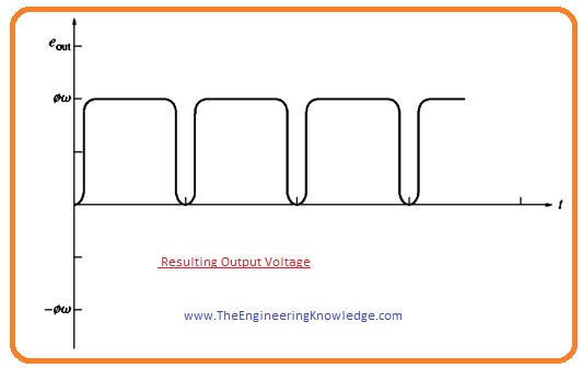
- Above we see that the waveform at the output of loop was like an alternating current waveform. As we are working for dc machines so the output should be dc for this we discuss the given below figure and see how a waveform will convert into a dc voltage.
- In this figure you can see that the at output terminals of the rotating loop to split rings are attached and also called commentators.
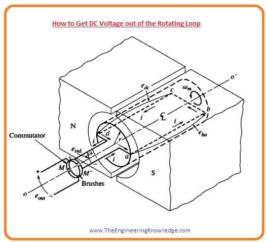
- Due to these commentators, the output will be dc waveform it shown in given figure.
- The conversion of ac waveform to dc is known as the commutation. These commutators are connected with the carbon brushes that provide current to the load and reduces the sparking at these terminals.
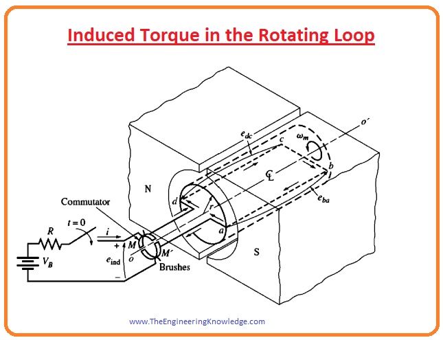
Induced Torque in the Rotating Loop
- For an understanding of torque induced in the rotating loop, we attach the battery with the input terminals of the machine. This configuration is shown in this figure.
- To find the value of torque induced in the machine we discuss this given below equation.
- For the calculation for total torque induced in the machine, we will find the torque at each side of the loop and then add all these torque values to get net torque.
- The force applied on every side of the loop will be given as.
F=i(lxB)
- And torque will be given as.
T = rFsinø
- In this equation, the ‘ø’ is the angle between the force applied and r. now we see torque on every side of the loop and will add all these torques.
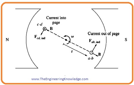
Side ab:
- The direction of current passing through this section is out of the plane, so the force on this side will be given as.
Fab= i(lxB)
=ilB tangent to rotation direction.
- The value of torque at this side will be given as.
Tab = rF sinø
=r(iIB) sin 900
=rilB counterclockwise
side bc:
- At this side, the direction of the current is from upper left to lower right as you can see in the figure.
- So force at this side is given as.
Fbc = i(lxB)
=0 as I is parallel to B
So, tbc = 0
Side cd:
- At this side direction of current into the plane.so the force is given as.
Fcd = i(l X B ) tangent to rotation direction
- Torque is given as.
Tcd =rF sinø
=r(iIB) sin 900
=rilB
Side da:
- On this side the current direction is from upper left to lower right, so the force is given as.
Fda = i(I XB)
=0 as I is parallel to B
tda= 0
tind= tab + tbc + tcd + tda
tind= 2rilB under the pole faces
=0 outside the pole edges
- If we put Ap =πrl and ø=ApB, then the equation of torque will be.
- tind = (2/π) øi under the pole faces
- = 0 beyond the pole edges
- So the torque in any dc machine is the multiple of flux with current and constant.
- From this equation, we can conclude that torque in dc machines torque relies on these three factors.
- Flux of machine
- A current passing through the machine
- constantly expressive of the structure of the machine
Friends that is the detailed post on the Simple Rotating Loop between Curved Pole Faces I have mentioned each and everything related to this post. If you have any question ask in the comments. See you in the next tutorial. Have a good day.