 Hello, friends welcome to new tutorial. In this post, we will have a detailed look at Theory of Operation of Real Single-Phase Transformers. The transformer is an electric instrument that used to change power levels from high to low or low to high according to circuitry requirements. This process is done through the application of mutual induction in that drive.
During power transformation, the frequency of the system remains constant just vary the voltage level. here we discuss the different parameters that occur in the signal phase transformer during power transformation. So let get started with Theory of Operation of Real Single-Phase Transformers.
Theory of Operation of Real Single-Phase Transformers
- For the construction of real transformer, there is a need of 2 or more than 2 windings wounded at the core created through the ferromagnetic substance.
- The features of real transformer is somewhat is like the ideal transformer but not completely.
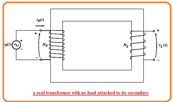
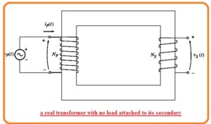
- For a practical understanding of the function of real transformer look at the below figure.
- The diagram indicates the transformer comprises of 2 windings wounded at the core.
- The input or primary windings of the transformer is linked to the ac supply and other to is not linked to load or open-circuited.
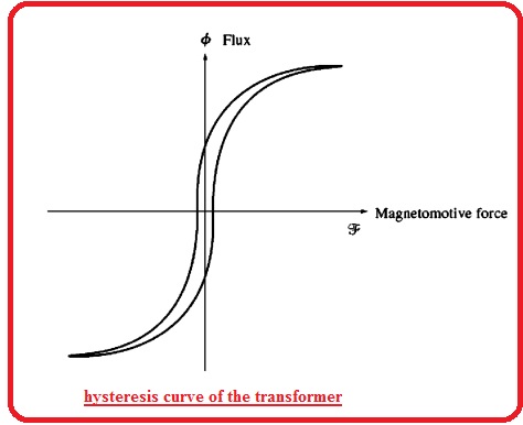
- The hysteresis graph form of this can seen here.
- according to faraday law the equation of transformer will be
eind = dλ/dt
- In this equation, λ is the linkage of flux in the windings about the voltage ie produced. The flux linkage is the summation of flux through every turn of winding

- The net flux in the windings is not only Nθ here N turns of coils since the flux in everyone turns is not like to the flux of other turns according to the location fo turns in the windings
- Though it is certain to explain the average flux per unit turn in windings. If the net flux linkage in every turn of windings is λ and if there is N turns the average flux for one turn is here.

Voltage Ratio of Transformer
- If the voltage of supply in the above diagram is Vp(t) then the voltage is positioned directly about the windings of primary windings of the transformer.
What will effect of transformer behave for voltage given
- Faraday law says that when above equation is resolved for average flux denotes in the primary windings of the transformer the outcomes is.
q
- This equation indicates that the average flux in coil is proportionate to the integral of voltage given to the coil and constant proportionally is inverse of turns at primary side 1/Np.
- This flux is exist in the primary windings of the transformer what will be its effect at secondary winding.
- There is not total flux generation in the primary move from the secondary windings but its some portion left out the core
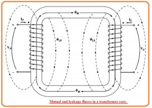
- The part of flux that left the core of the transformer is known as leakage flux. The flux in the primary windings of the transformer can be parted in 2 parts first one is the mutual flux that stay in the core and koins two windings and small leakage flux that goes through the primary coil.

- Here is like the partition of flux in the second winding among the mutual flux and leakage flux that moves through the secondary windings and not move through air crossing the primary windings.

- The partition of average primary flux in mutual and leakage parts. Faraday law for primary circuitry can be explained here.
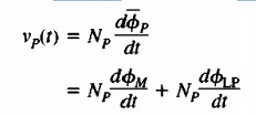
- The ist component in this expression is known as ep(t) and 2nd component can call eLP(t). The above equation also mentions here.
![]()
- The voltage of secondary windings of transformer also defines through Faraday law.
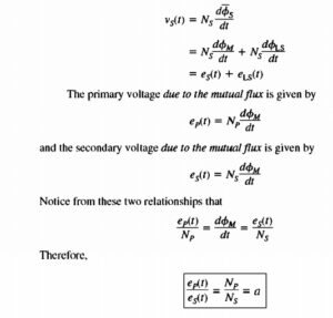
Magnetization Current of Real Transformer
- If ac supply is linked to the transformer can seen in belwo figure.
- The current passing in the primary windings when there is open circuitry at secondary.
- The current is current needed to generate flux in real core of ferromagnetic. That comprises of 2 elements.
- The magnetization current iM that is currently needed to generate the flux in the transformer core.
- The cire losses that are eddy current and hysteresis loss is current needed to create for hysteresis and eddy current losses.
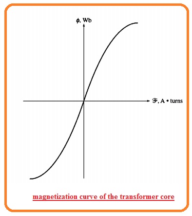
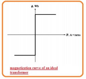
- The diagram shown below indices the magnetization curve of the transformer core.
- If flux in the transformer is core is found then the magnitude of magnetization current can be known through above diagram.
- Through lifting the factor of leakage flux the average flux in the core is given through here


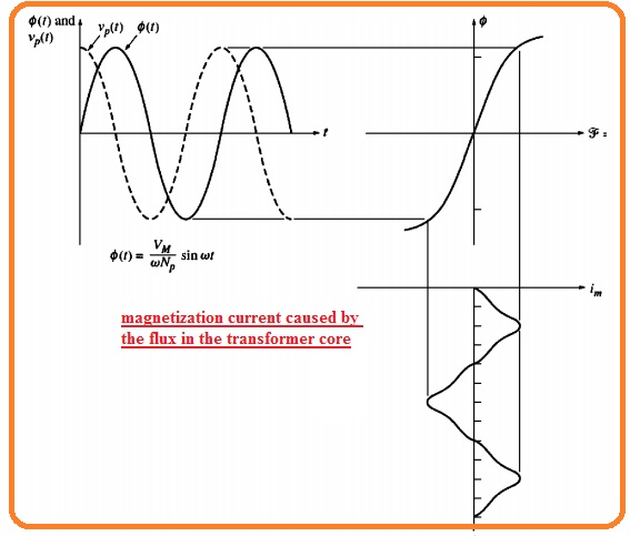
- If the parameters of current needed to generate the resultant flux in below figure is like to the flux in the core at different time interval it is certain to make a graph of magnetizing current in the coil of core.
- The graph can seen here
- Note that given point for magnetizing current.
- The magnetization current show is not like the sine wave. The large frequency elements in the magnetization current is caused to magnetic saturation in the transformer core.
- When the peak flux get the saturation point in the core the small increment in the peak flux needed the high increment in the peak magnetization current.
- The basic element of magnetization current lagging the voltage given at the core through ninety degrees,
- The large frequency element in the magnetization current can will be very high as compared to basic element. In normal the more the core of transform is going to the saturation the high value of harmonic elements are.
- The other element of no-load current in a transformer is current is needed to give the power to create hysteresis and eddy current in the core.
- It is the core loss current. Suppose that flux in core is sine shape because the eddy current in the core are proportionate to dθ/dt the eddy current is high when the flux in the core is moving is zero.
- So the core losses current is highest like flux is zero. The net current needed to create for core losses is can seen here.
- Note that windings about the core loss is given here.
- The core losses current is not linear since the nonlinear behavior of hysterics.
- The basic element of core losses current is in phase ot the voltage givne at the core.
- The net no load current tin the core is known as excitation current of the transformer. It is like the summation of magnetization current and core loss current in the core.
![]()
Current Ratio of transformer and Dot Convention
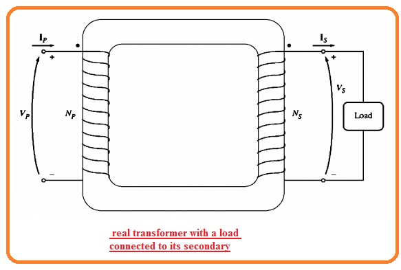
- Let us assume that the load is attached with the secondary side. The corresponding circuitry can seen here.
- Note that dots at the windings of the transformer. Like the ideal transformer dots mentioned to find the polarity of voltage and current in core.
- The importance of dot convention is that current passing in the dotted point of coil generates a positive MMF and current passing in the non dotted point makes negative mmf
- So 2 current passing in the dotted point of resultant coils make mmf which added. If current passing in the dotted point of windings and one part of current coming out from dotted point then mmf will minus though every other
- In this condition the below figure shown the primary current generates a positive mmf Fp=NpIp and secondary current genets negative mmf Fp=-NpIp
- So the total mmf at the core is

- Here R reluctance of core of the transformer. Since the reluctance of the highly designed transformer core is almost 0 till the core is saturated the relation among the primary and secondary winding current is given here.
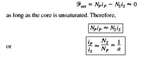
- It is the factor that mmf force in the core is almost 0 that offers the dot convention. For mmf to 0 current should pass in one dot point and comes out from another dot point.
- The voltage should be created in the similar manner according to the dotted point at every winding to operate the current in a given direction
That is detailed post about Theory of Operation of Real Single-Phase Transformers if you have any further query ask in the comments. Thanks for reading have a nice day.


