 Hi, reader, I hope you all are doing great. In today’s post, we will have a detailed look at How to Troubleshoot OP-Amp Circuits. As ICs created with the operational amplifier can be easily handled, and operate well in normal conditions but some faults exist in these modules with In today’s post, we will have a detailed look at How to Troubleshoot OP-Amp Circuits. As ICs created with the operational amplifier can be easily handled, operate well in normal conditions but some faults exist in these modules with In today’s post, we will have a detailed look at How to Troubleshoot OP-Amp Circuits. As ICs created with the operational amplifier can be easily handled, operate well in normal conditions but some faults exist in these modules with time. One category if the inner fault is the state when the output of the operational amplifier is in saturation region which causes the high or low level at output irrespective of variation in the input signal.
With that there is different types of element damaging occurs that cause different types of faults in circuits using an operational amplifier. In today’s post, we will discuss about these faults and learn how to troubleshoot these faults. So let’s get started with How to Troubleshoot OP-Amp Circuits.
How to Troubleshoot OP-Amp Circuits
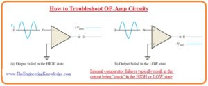
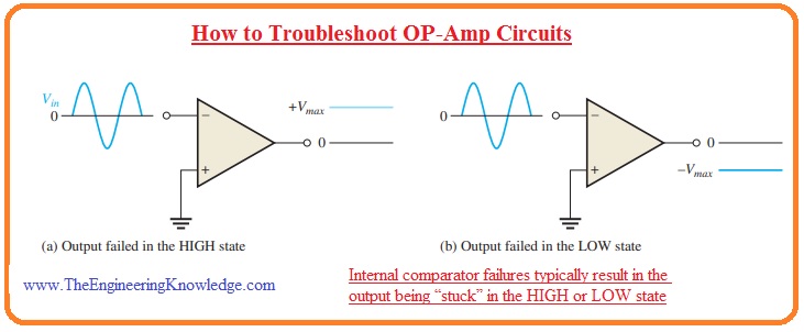
- The below figure describes the inner fault of comparator circuitry which generates stuck results.
Symptoms of Outer Component Failures in Comparator Circuits
- The comparator circuit having Zener grounding and hysteresis configure is drawn in the below figure.
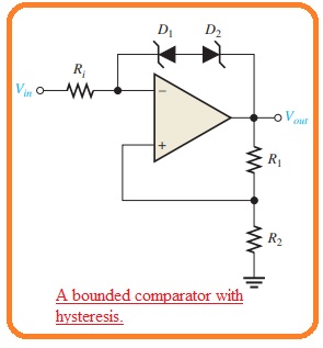
- For damaging of the operational amplifier the Zener diode or any resistance can be damaged.
- For instance, assume that there is one diode that has an open circuit. It causes the separation of both Zener diode and circuitry will operate like an unbounded comparator. It can be seen in the below figure denoted as a.
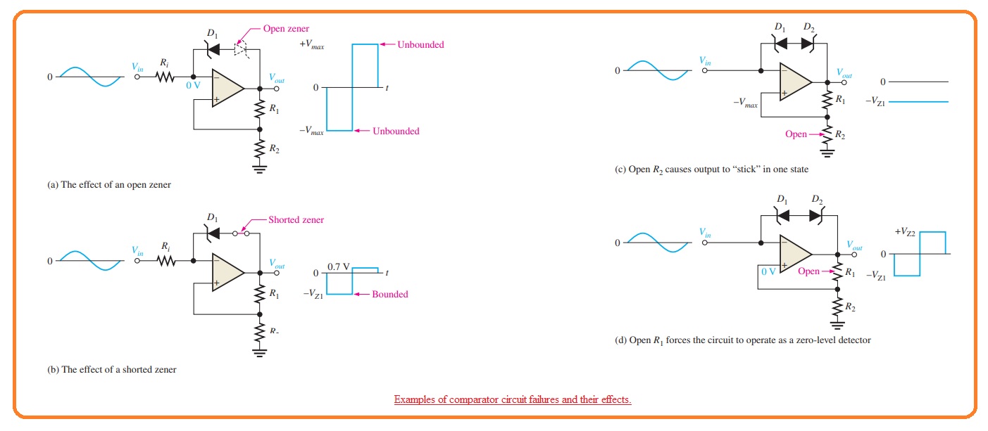
- In the case of short circuit diode, the output is restricted at the value of Zener voltage and has only a single direction according to diode that is operating it is shown in figure denoted as b.
- In the case of other directions, the voltage at the output is forward diode voltage.
- Let us assume that resistance R2 is an open circuit so the voltage at the output terminal will move back to the non-inverting terminal and as the voltage at the input is not larger than the output voltage the component will retain its bounded condition.
- This situation causes faults in an operational amplifier.
- Now suppose that resistance R1 is an open circuit it causes the noninverting input close to the grounded potential and it results in the circuitry to work like 0 level detector. Both of these states are shown in the figure denoted as c and d.
Symptoms of Element Damaging in Summing Amplifiers
- If any resistance at the input terminal has unit gain, then the summing amplifier circuit will get opened, and the output will decrease to the general value through the quantity of voltage given at the input terminal, which is an open circuit.
- The net output voltage will be the addition of the other remaining input voltages.
- If the gain of the summing amplifier is non-unity, then open input resistance results in the output decreasing the general value by the quantity that is equal to the multiple gain with the voltage at an input in case of an open circuit.
What are the common mistakes in op-amps?
- The common error for operating operational amplifiers is to use a gain less than unity that tharesults ined unstable oscillation affecting the circuit. If operational amplifiers are used for comparators.
What are the error sources of op-amps?
- The main errors are input bias current, input offset current, input offset voltage, PSRR, and finite input impedance.
What is the common problem of amplifiers?
- The accurate maintenance and repair of amplifiers is important for performance maintenance and avoiding any damage. The main issues that occur for amplifiers are no sound, distorted sound, low output hum, and overheating.
What is integrator error in op-amp?
- The main causes for error in integrators are offset and drift of amplifiers.
What are the three types of amplifiers?
- Voltage amplifiers get voltage and generate output voltage. Current amplifiers get current input and generate current output. Transconductance amplifiers transform voltage input with current output.
What is common mode rejection in an amplifier?
- The common mode rejection ratio of differential amplifiers is a value that is used for defining features of devices to reject common-mode signals. That shows the same and in-phase on both inputs.
What is the cutoff frequency of an op-amp?
- If operational amplifiers have unity gain, the cutoff frequency is 45 MHz; that is called the unit gain bandwidth of operational amplifiers. If operational amplifiers come with a closed-loop gain of 100, the cutoff frequency is 800 kHz (80 MHz/100).
So friends that is a detailed post about How to Troubleshoot OP-Amp Circuits I have explained each and every parameter related to this post. IF you have any further query ask in the comments. Thanks for reading