 Hello, readers welcome to the new post. In this post, we will discuss the Difference Between Shunt and Series Voltage regulators. The voltage regulator is electronic equipment that used the voltage of the power supply to the required value. To get the required voltage of projects and circuit voltage regulators are used. The output of the voltage regulator is constant whether there is changes are existing at the input side. Its main feature is to save the device connected to it from damage.
The basic operation of voltage regulators is to maintain the output voltage irrespective of the change in voltage at the input. It also helps to maintain the output voltage according to the needs of the circuits. Commonly used types of dc voltage regulators are Shunt and Series Voltage regulators on the basis of construction. Here we will discuss different parameters that provide differences. So let’s get started.
What is Shunt Regulators
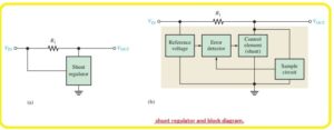
- A simple configuration of shunt regulator can be seen in the figure below labeled as a’ and the circuit components are shown in the block diagram labeled as b’.
- In this shunt regulator configuration, the control component is a transistor in parallel combination with the load can be seen in the below figure.
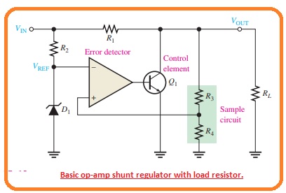
- Resistor R1 is connected in series with the load. The function of the circuit is like that of a series regulator except that the regulation is achieved by regulating the current passing through the parallel transistor Q1.
When the value of the output voltage decreases due to changes in the input voltage or load current generated by the change in load resistance, it can be seen in the figure below.
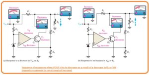
- The decay is monitored by resistors R3 and R4 and is given to the non-inverting input.
The resulting differential voltage lowers the output of the operational amplifier to decrease the value of its collector current and increase the collector voltage. - So the real voltage drop is overcome by this increment and keeps the output value almost constant.
The opposite process occurs when the output increases, as seen in the figure above.
With a constant value of the current IL and VOut, a change in the input voltage generates a change in the side current.
ΔIS=VIN/R1 - a constant Vin and Vout load current variation cause the reverse shunt current variation. If there is an increase in current IL and a decrease in Is.
ΔIS = -ΔIL - The side regulator is less efficient than the series category but provides short-circuit protection.
If the output is shorted, the load current is limited by the series resistance to the extreme point as indicated.
IL(max)=VIN/R1
What is Series Voltage Regulator
- In below figure, you can see the basic configuration of the linear regulator denoted as the main element used in the circuitry can be seen in figure denoted as b
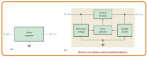
- The control component is a pass transistor in series combination with a load between input and output.
The output circuit detects the change in the output voltage. The fault sensor compares between the sample voltage and the reference voltage and causes the controller to compensate to maintain a constant output voltage.
The basic controller of a series of operational amplifiers is drawn in the figure below.
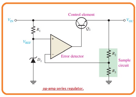
Series Voltage Regulator Working
- The function of the series regulator is explained in the below figure.
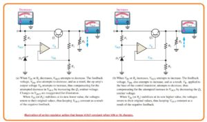
- A resistive voltage divider circuit creates resistance R2 and R3 and detects changes in the output voltage.
when the output decreases as shown in the figure above because the decrease in Vin and the increase in current IL causes due to the decrease in resistance RL.
A proportional reduction in voltage is applied to the inverting terminal of the operational amplifier with a voltage divider.
Because the Zener diode keeps the input of the second op amp close to a constant reference voltage, a small differential voltage is created across the op amp inputs. - this differential voltage is amplified and the output voltage of the op amp VB is increased.
This increment is given to the base of transistor Q1 and causes the emitter voltage to increase again until the voltage at the inverting input equals the reference voltage.
This process compensates for the attempt to reduce the output voltage and keeps it at a constant level.
Power transistor Q1 is normally used with a heatsink combination because it can handle the load current.
The opposite process occurs when the output goes incremental, as seen in the figure labeled b.
The operational amplifier in the series regulator is connected as a non-inverting amplifier, here the reference voltage is the input voltage at the non-inverting terminal and the voltage divider R2/R3 forms a negative feedback circuit.
The voltage gain in the closed loop is given as.
Acl = 1 +R2/R3 - So the regulated output voltage of the series regulator is given as.
- VOUT=(1+R2/R3)VREF
- According to this analysis, we can observe that the output voltage is located with the Zener voltage and the resistance of R2 and R3

Difference Between Shunt and Series Voltage Regulators
| Feature | Shunt Voltage Regulator | Series Voltage Regulator |
|---|---|---|
| Working Principle | Uses shunt element to regulate voltage | Uses series element to regulate voltage |
| Characteristics | Output voltage is constant and independent of load current | Output voltage is constant and independent of load current |
| Efficiency | Low efficiency | High efficiency |
| Power Capacity | Suitable for low power applications | Suitable for high power applications |
| Heat Generation | Generates more heat | Generates less heat |
| Complexity | Simple and easy to design | Complex |
| Response Time | Fast | Slower than shunt regulators |
| Cost | Low cost | Higher cost than shunt regulators |
- The shunt voltage regulator is attached in parallel configuration with the load and series regulator in a series combination
- The shunt voltage regulator provides good regulation for high current using loads and the series voltage regulator not has good operation for high currents
- For high loads shunt regulator is used and for heavy loads series regulator used
- The constant value of output for the shunt regulator and non-constant for the series regulator
- The Shunt regulator is a high voltage and low current instrument and the series regulator is a high current low voltage device
- For low curent shunt as good efficiency and for series regulators is effective for high loads currents
That is all about the Difference Between Shunt and Series Voltage Regulator all details has explained. If you have any questions ask them here

