 Hello, readers welcome to new post. Today we will discuss Constant Current DC Power Supply Circuit. The constant current power supply is considered as 4 pins active device. Its input is denoted as dc volts source for basic current regulators, and it denotes the AC line voltage for such supply that comes with rectifiers and filters. In the case of practical operation transformer, rectifiers and filters is used for every device to generate dc supply. In the end, the power controller is connected.
In a circuit of constant power supply, there is the dc power source that operates the series pass transformer that is regulated through the high-gain operational amplifier. The feedback signals get through the use of shunt resistance Rs. I
Working Principle of Power Supply Circuit
- There is current produced due to voltages and no other option for that, therefore, to make constant current through the device there must have to use negative feedback and transform the load moving through the circuit in volts.
- Normally there is a simple circuit to transform current in a voltage that has a small value of resistance normally 0.1 ohms.
- The voltage value of this resistance will directly be proportional to the current will help us to solve the issue of the current use in the circuit.
- The voltage across the resistance is provided to the negative input of the operational amplifier and a fixed value of volts is given at the positive pin of the amplifier.
- The output of the operational amplifier is given to the base of the power transistor that regulates the current passing through the circuit.
- The operational amplifier in circuitry in closed loop form since negative input and output are linked with each other through the capacitor denoted Q3 in the circuit.
- Here you can see a circuit of constant current power supply and its detailed working explained below
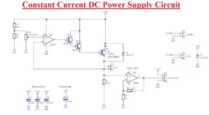
- We have to make the constant current supply of one-ampere current and a one-ohm load is attached with the output.
- If the one-ampere current passes through circuitry so we must have to see volts of 0.1 volts about the 0.1-ohm resistance. For this value of the potentiometer is such that a voltage of 0.1V is provided to U1A positive terminal.
- If the current across the load is less than one ampere, then voltage about 0.1-ohm resistance is also less than 0.1 volts and it can be observed at the negative terminal of U1A.
- As the positive terminal is greater than the negative pin operational amplifier will be positive and so the conduction of transistor Q3 will be increased.
- Due to the high conduction of transistor Q3 permits to passing of a larger current through the load and 0.1-ohm resistance.
- If current passes through resistance is larger than one ampere in results voltage about 0.1-ohm resistance larger than 0.1 volts.
- It indicates that negative input to the operational amplifier UA1 is larger than positive input and in a result, operational is now had more negative value.
- The decrement in output volts causes in conduction of transistorQ3. So current passing through load decreases and also across a resistance of 0.1 ohm
- To measure the current passing through the load voltmeter is attached to the amplifier U1B. The main function of the amplifier is to enhance the volts about the 0.1-ohm resistance to such a value that can be read easily through using LED display
- D1 diode is used to stop EMF spikes which can be made through load through damage of Q3 transistor. The transistor Q3 must be in a To-2 structure with having some heat dissipation for current on one hundred milliampere current and must have a heatsink and fan to handle the current of more than one ampere
- In the below figure, you can see the PCB layout of the constant current supply
Component of Project
- The main component of this circuit are listed here
- two 10k Resistances
- Two one Kilo resistances
- 0.1 Resistance
- three 100nF capacitor
- 1 470uF capacitor
- two 1N41418 Diode
- LM358
- one 8 Dual inline packaging Socket
- 100K linear potentiometer
- 2N3904 Transistor
- Voltmeter
- JLCPCB PCB
- JLCPCB is the most reliable and trustworthy with a high-quality experienced engineer team who supplies PCB and based in China.
They have been serving their customers for 15 years, offering them high-quality printed circuit boards, assembly services, and fast delivery on time. - If you want to get a simple level of boards for small quantities to mass production, JLCPCB is considered to be the best choice for you.
- Founded in 2006, it has been at the forefront of the PCB industry. With more than 15 years of continuous innovation and improvement based on customer needs, they have grown rapidly to become the world’s leading printed circuit board manufacturer, providing rapid production of highly reliable and cost-effective printed circuit boards and creating the best customer experience in the industry.
- From JLCPCB you can get 1 to 2 layers of PCB in five pieces for just 2$ with dimensions of 100 by 100 mm with FR4, aluminum, and lead-free features. Also, have $56/m2 for batch production
- The material FR-4 Standard Tg 130-140/ Tg 155 can also get from JLCPCB. The dielectric constant used to JLCPCB is 7628 Prepreg 4.6 3313 Prepreg 4.05 2116 Prepreg 4.25.
- You can also get the panels of your PCB from JLCPCB panelization services at good rates. Their advanced PCB technology makes sure to provide high-precision boards suitable for industrial, military, aerospace, and medical applications.
Constant Current DC Power Supply Construction
- In this project, we are getting power from ATX or older version personal computer since the required value of current can get at less volts.
- The circuit construction is discussed step by step in an open style
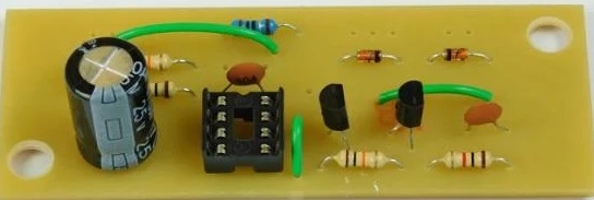
- In the below figure you can see that all components used in this project are positioned on the PCB board get from JLCPCB and still need to wired up
- In figure after making the connection of wires side view of constant current power supply can be seen
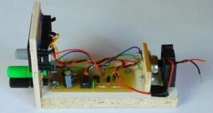
- Wiring to front panel is seen here
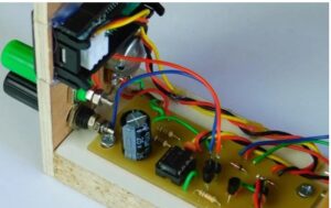
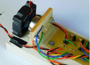
- Fans-assisted cooling and To-3 mounting is shown in below diagram
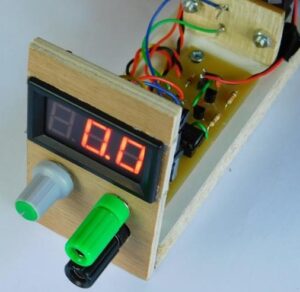
- Front display, output prongs, and potentiometer of our supply shown below
Advantages
- The constant current device is used to give the constant value of current as the output is varying. To work this power supply in constant mode, adjust the power supply to a voltage value larger than the required volts for the circuit
- It mostly used for laser and electroplating applications
That is all about the Constant Current DC Power Supply Project Circuit all details of this project have been covered if you have any queries ask in the comments. Also not forget the PCB from the best PCB supplier JLCPCB at good rates and high quality


