 Hello, readers welcome to the new post. Here we will discuss Solar Battery Charger Circuit. Solar technology currently has become very common and almost all big industry homes and buildings are transforming to solar energy. With that solar operating devices are prevalent in common uses and at an advanced level. Solar operating devices are also in use at space stations where there is no electricity.
The first-time photovoltaic effect was introduced by Edmond Becquerel when he finds the generation of current and volts through the material placed in the light. Due to this process first, the solar cell was created in 1893 by Charles Fritts. Currently, high-level and advanced solar panels are used in industries and homes. They are operating the different small level devices to high machines in industries.
In today’s post, we will make a circuit of a battery charger that is operated on solar energy. Through chargers, we can operate devices based on electronics. This project is created through the collaboration of JLCPCB
Working Principle of Solar Panels
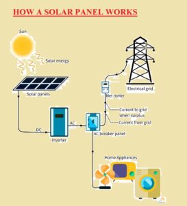
- The solar panel system is based on photovoltaics that gets the sunlight energy and converts it into current. A normal solar panel system has four parts that are solar panel, inverter net meter, and AC breaker panel.
- Solar panels are considered as the main part of the electrical system. They come with the feature of light absorption and convert it into the current.
- When sunlight collides on the panels material of the panels absorbed the energy and generates the dc current.
- The dc generated has a fluctuation and unsteady nature so not provided directly to appliances. This dc current is converter into AC through use of inverters
- The inverter is an electrical instrument that transforms the DC into AC.
- In simple form operation of solar panels is based on the transistor working. The material of the panel is N type and P material that has holes and electrons.
- When photons of light collided on the PN junction electrons get energy and move to holes and due to movement of electrons current produces
HOW TO BUILD A SOLAR-POWERED BATTERY CHARGER
First, we will discuss the specification of our circuit
Solar Charger Circuit Features
- We using a solar panel of 4.5 watt
- Output volts are 5V and 12 V
- Voltage regulation +/- 100mV
- The highest output current is about 0.29 amperes
- Input volts 7 to 30 volts
Solar Charger Components
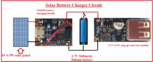
- Below figure, you can the diagram of our circuit with components listed here
- 3.7V 2600mAh lithium battery
- TP4056 battery charging module
- 6V 4.5W solar panel
- 3.7V to 5V step up converter
- Slide Switch
- PCB from JLCPCB
- In this project, we used PCB from the JLCPCB which is the best in all services, and from JLCPCB you can get 2-, 4-, and 6-layer boards for just 2$. They also have introduced their new purple solder mask with that you can also get 3D printing and services at very low rates and great quality. Their main motive is to not be comprised on the quality of their board.
- New users enjoy $54 free coupons after signing up at JLCPCB successfully
- JLCPCB offers high-quality boards at affordable prices. They are compatible with good services for various projects for their customers. Users always prefer high-quality products. JLCPCB offers five printed circuit boards for just two dollars. It tries to fulfill the user’s requests on a regular basis.
- Their easy-to-use online ordering system, professional and efficient customer service, digital manufacturing technology, fully automatic production lines, and stable logistics partners take every step to deliver your PCB faster.

Circuit Explanation
- In this project, we will make a solar power battery charger that will provide power to devices operating 5V through USB cables such as mobile phones and Arduino-based projects.
- Here you can see the circuit diagram of the project.

- In this project, we used two lithium batteries having features of 3.7V and 2600mA that will store the power generated by the solar panel. For getting the power from the solar panel and charging the battery there is a TP4056 battery charging module used. The output of this charger module is about 4.5 to 6 volts after regulation is provided to the battery. Make sure that your solar panel is providing six volts at the output.
- I used 6V 4.5-Watt solar panel in this project. The value of output current from this panel is about 4.5W / 6V = 750mA according to the formula P=VI
- Let’s suppose that we have 85 percent efficiency then the current will be 650mA. As two batteries are in parallel configuration so have a total capacity of 5200mAH to charge these batteries we need 8.1 hours according to this formula 5200mAH / 640mA = 8.1The operating volts for battery are 3.7 volts so there must be step up these volts up to 5 volts to send USB charging. For this purpose, the 3.7V to 5V step-up converter module used in this circuit
- This module uses 2 amperes current but the highest current for TP4056 battery charger is one ampere. If you connect the Device that uses 2-ampere current has a chance to burn the TP4056 battery charger
- In below figure, you can see the complete circuit of the project
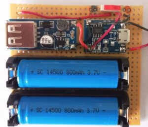
- Red and black wires are linked with the solar panels and a slide switch is used to one and off the charger
How to Install Solar Panels
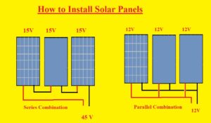
- Solar panels now are used at each industry and home of powering appliances. There are two connection configurations that are used for the installation of panels on the basis of current and volt.
- The first one is a parallel configuration that has the same volts about each panel but the current of each panel added and at the output, we have high current than the individual panel
- But if we have a series configuration then volts will add and current will have the same value. So according to device and appliances operation, we can make the connection of our panels to operate devices that has different current and volts values
- Like this in the above solar power battery charger circuit, we must also have a configuration in mind according to high current and volts.
How to Calculate Solar Panel Size
- To design a solar panel first we have to know the daily use of KWh let’s suppose we have a small home and then we find the ratings of all appliances used in the home.
- After that, we use the given below formula to find the watt-hour of every device.
- Watt- hour= watt x hour appliance used
- Let’s suppose we have a 700-watt refrigerator that works for 10 hours in a single day then its watt hour will be
- =700 x 10= 7000Wh
- Let’s suppose have losses and inefficiently of thirty percent then multiplying 1.3 with 7000wh we have
- 7000 x 1.3= 9100
- After we have daily hours for the sunlight that can be found through the net and depends on the location. After calculating the daily hours of light divide it by the watt hour above calculated. Let’s suppose we have 7 hours sunlight then panel size will be
- 9100wh/7 hours= 1300 watt
- So, we need to install the 1300-watt solar panel in our home. Instead of single panels, we can use more panels after dividing the watts.
- This calculation will you to design your solar power battery charger
Advantages
- Advantages of this circuit are listed here
- It has very less battery discharge when no sunlight exists
- Its circuit is simple and less expensive components are used
- can get variable output volts
That is all about the Solar Battery Charger Circuit all details have explained. If you have any queries, ask in the comments. Thanks for reading


