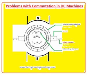
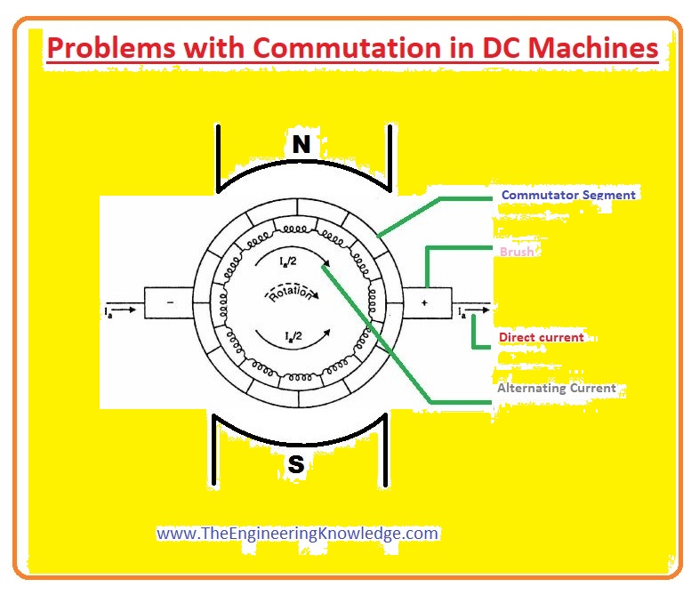
Hello, friends, I hope all of you are having fun in your life. In today’s tutorial, we will discuss the commutation problems in DC machines. In DC machines the voltage produced is an AC voltage, like the output voltage of AC generators such as induction generators and synchronous generators. For the generation of these voltages, we have discussed the rotation of a simple loop in a field. For the conversion of AC voltage produced in the DC machines, half of the ring is connected. This split ring is known as a commutator, and the process of AC to DC conversion is called commutation.
During this commutation, there are some problems that occur that affect the AC to DC conversion process. In today’s post, we will have a look at these issues that disturb the commutation and also discuss some solutions to these problems. So let’s get started with problems with commutation in DC Machines.
Commutation Problems in DC Machines
2 main issues disturb the commutation process. We will discuss these two with details and solutions to these problems.
L di/dt voltages
So friends, let’s first discuss Armature’s reaction.
If we connect the input supply at the stator of a DC machine and also rotate the rotor of the machine with the exterior prime mover, during rotation the rotor will link with the flux of the stator field that will induce a voltage in the rotor.
The voltage will be AC and be converted into DC by the commutator attached to the rotor. Now if we connect some load with the rotor of a machine, it will use some amount of current that will pass through the armature or rotor windings.
Due to this current, there will be another magnetic field that will affect the field of the stator.
This disturbance of the armature field to the original field of the stator is known as armature reaction.
There are two main issues that occur due to this armature reaction.
Neutral-Plane Shift
Flux Weakening
Neutral plane shift
- The ist issue caused by the armature reaction is a neutral plane shift. In a DC machine, a position where the rotation direction of the rotor is parallel to the field lines is known as the magnetic neutral plane.
- In this plane, voltage production in the armature windings is zero.
- For an understanding of the neutral plane shift problem, we discuss the figure given below, which has 2-pole DC machines.
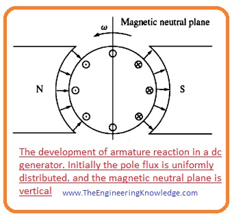
You can see that flux is uniform over the complete machine. The voltage induced in the winding under the North Pole is out of the page, and the voltage to induce in the rotor windings under the South Pole has direction into the page.
You can see that in the above-given figure the direction of the neutral plane is at ninety degrees. It is when there is no load linked with the machine.
Let’s assume that we have connected a load with this machine; it behaves like a generator. Current will flow in an outward direction from the positive output terminal; thus, the current direction is out of the page for windings under the effect of north poles and into the page for windings under the effect of south poles.
Due to this current, there will be field produce in the windings of the rotor; it is shown in this given figure.
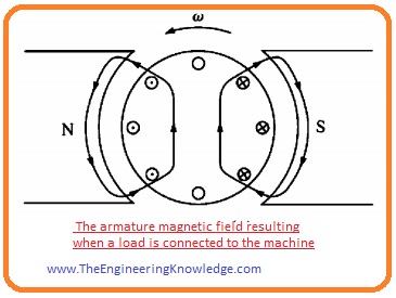
- This field of the rotor will interact with the field generated by the stator of the generator. At some points, these two fields will add up with each other, and at some points will cancel each other.
- The final effect of these two fields is shown in the given figure.
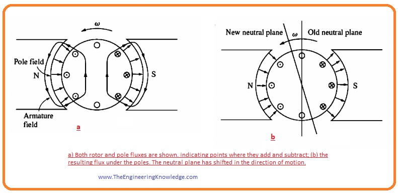
You can see that the point where the voltage produced is 0, where the neutral plane shift has occurred.
As we are working on the DC generator, you can observe that the neutral plane shift is in the direction in which the generator is rotating.
But if it is a DC motor, then the neutral plane shift will be opposite to the direction of rotation.
In simple words, the plane shift for a generator is in the direction of rotation, and for a motor, it is in the opposite direction of rotation.
The plane shift relies on the quantity of current drawn from the rotor and the connected.
So what’s the big deal about the neutral-plane shift?
The commutator necessity short-circuited commutator segments at the instant when the voltage across them is 0.
If the brushes are fixed to short-out conductors in the perpendicular plane, then the voltage among segments is certainly 0 till the load is attached.
When a load is attached, the neutral plane shifts and the brushes short-circuit commutator segments with a specific value of voltage, across them.
The consequence is a current now flowing among the shorted-out segments and huge sparks at the brushes when the current is disturbed as the brush leaves a segment. The final outcome is arcing and sparking at the brushes.
It is a serious problem, as it leads to severely decreased brush life, pitting of the commutator segments, and highly enhanced repair charges.
Note that this issue cannot be removed even by inserting the brushes over the full-load neutral plane since sparking will occur at no-load condition
Flux weakening Armature Reaction
- The issue caused by the armature reaction is the weakening of flux. For an understanding of this issue, we discuss this given below figure.
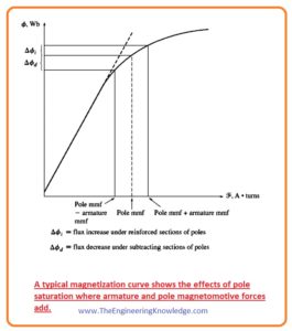
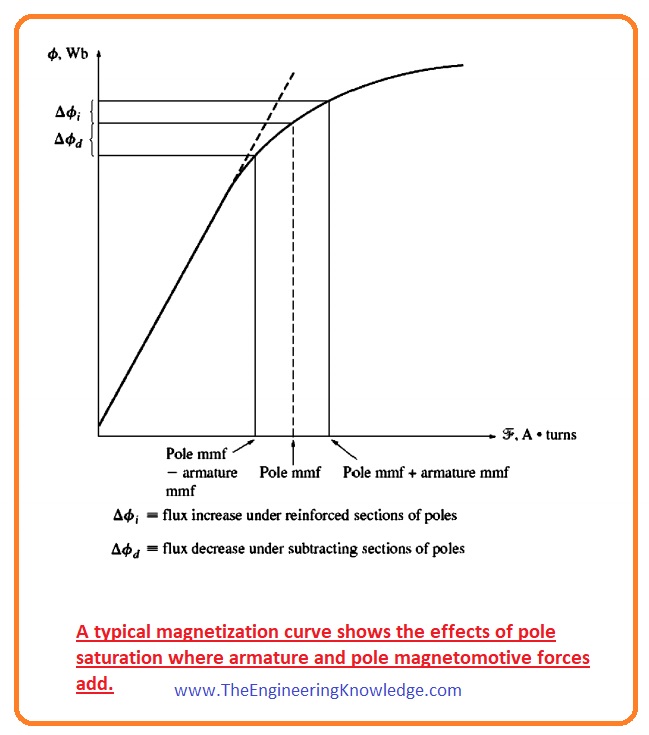
- Most machines work at flux near the saturation point. So at the point where the MMF of rotor adds up with the MMF of the poles at stator, there is less increment in total flux.
- But at a point where the MMF of the rotor is subtracted from the MMF of the poles, then a larger decrement occurs in the flux value.
- The final outcome is that the net value of flux over a complete pole will be lessened. You can see this in the given figure.

The weakening of flux is not good for both the motor and the generator. In generators, the output voltage of the generator decreases.
But in the case of the motor, this factor causes serious problems. With the decrement of a flux rotation speed of the motor, it also decreases.
Speed increment also increases the load connected with the motor, which causes a lessening of flux.
It is likely in some shunt DC motors to approach a running state as a consequence of flux decrement (weakening), where the speed of the motor increases till the machine is detached from the input supply or until it is damaged.
L di/dt Voltages
The 2nd issue that occurs during commutation is L di/dt, which occurs on the commutator and is also known as an inductive kick.
To understand this issue, let’s discuss this given figure. You can see commutator segments are attached to one another in a sequence, and the winding conductor is linked with them.
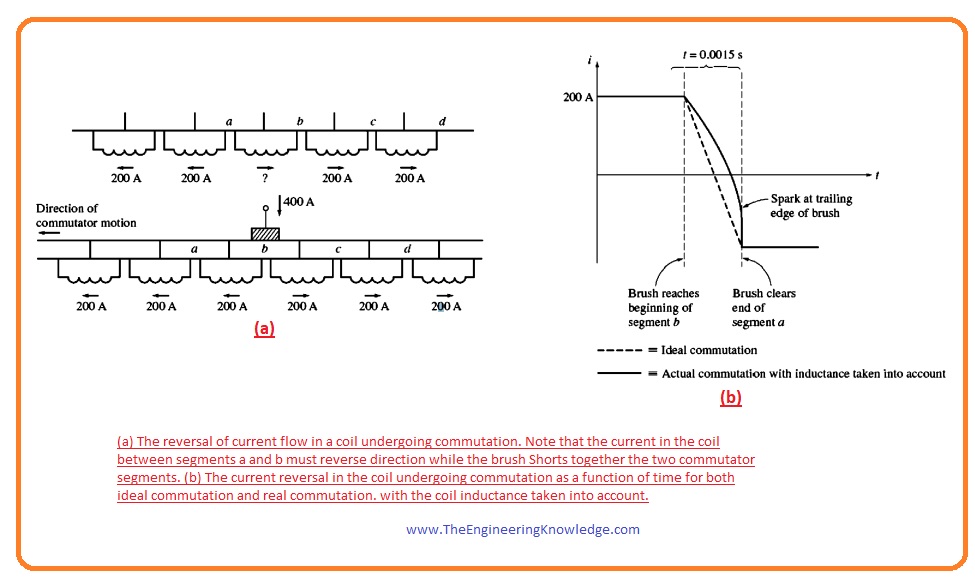
Let’s suppose that the current passing through the carbon brush is four hundred amperes; the current through every path is two hundred amperes.
Note that when the commutator is short-circuited, the current passing through the commutator will be reversed.
Here the question arises.
How fast must this reversal occur?
Let’s suppose that the machine is rotating at eight hundred revolutions per minute and has fifty commutator segments. Every commutator segment rotates under a brush and changes its position in (t = 0.0015 seconds.
di/dt = 400A/0.0015s = 266,667 A/s
With a small value of inductance, a very high value of Ldi/dt will be produced at the short-circuited commutator segments.
This higher voltage obviously causes sparking at the brushes of the machine, resulting in similar arcing problems that the neutral-plane shift causes.
So friends, that is the detailed post about problems with commutation in DC machines. I have mentioned the problems and their solutions. If you still have any queries, ask in the comments. See you in the next tutorial. Thanks for reading.