 Hello, fellows, I hope all of you are having fun in your life. In today’s tutorial, we will have a look at What is Armature Reaction. In the DC machine either it is DC generator or DC motor has 2 types of windings like ac machine, such as induction motor, induction generator, synchronous motor and synchronous generator. The first winding that is wound on the stator is known as field winding and the second is armature winding. In field winding, the main flux of the machine is produced.
In armature winding armature current passes that have its own flux in armature winding that interacts with the stator flux and decreases its effect that creates serious problems for the operation of a machine. This distortion in field winding due to the armature flux is known as armature reaction. This phenomena also affect the process of commutation in dc machines, in commutation AC is converted into DC by using commutators. In today’s post, we will have a look at the effects of armature reactions on electrical machines and will learn how to solve this issue. So let’s get started with What is Armature Reaction.
What is Armature Reaction
- As we discuss above the armature reaction is caused by the interaction of flux produced by the armature current that distorts the main flux of field winding.
- The flux of the armature winding creates two problems.
- It decreases the strength of field winding flux or demagnetizes it.
- Second is the cross-magnetization of field stator.
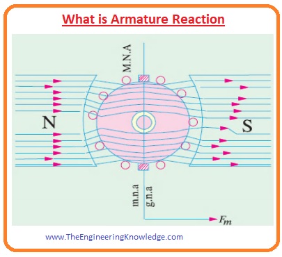
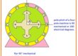
- In this given figure you can see the internal structure of bipolar generator when the value of armature current is zero and brushes of that generator are connected directly with armature winding, but in a normal case, there is a commutator between armature winding and brushes.
- It can be seen that the flux in this machine is uniform and parallel to the axis of poles, the line linking to poles is there axis.
- In dc machines there are 2 types of axis first is magnetic neutral axis (M.N.A) and the geometrical neutral axis (G.N.A).
- Geometrical Neutral Axis is described as the axis of rotation of the rotor where there is no voltage induced in the armature winding as a rotation of the rotor is parallel to flux lines.
- Magnetic neutral axis (M.N.A) is the axis that is 900 to the lines of flux moving through the armature winding (rotor).
- You can also note that the magnetic neutral axis (M.N.A) is in line with the geometrical neutral axis (G.N.A).
- The brushes of dc machines are connected along the magnetic neutral axis so this axis is also known as the commutation axis since the direction of armature current revered along this axis.
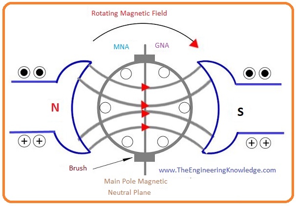
- In this given below the figure, you can see that a dc generator of 2 poles. Let’s suppose that there is no load connected with the generator so the value of armature current will be 0.
- The only flux in the generator is due to the poles of the generator. This flux is uniformly separated along the magnetic axis that is the line joining midpoints of north and south poles.
- The arrow indicates the direction of flux in the machine that is from north to the South Pole. You can see that the M.N.A is at 900 to the axis of the magnetic flux.
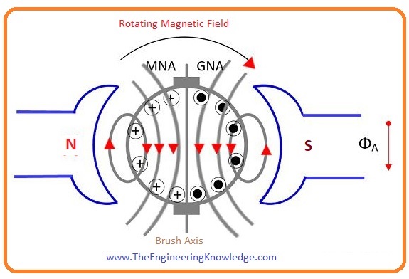
- Now suppose that the current is passing through the armature windings and poles of the stator are not producing flux because the current through them is zero.
- We can find the direct current passing through the armature conductor by the right-hand rule of Fleming.
- And the direction flux due to that current in a conductor can be fined by the cork-screw rule. This rule says that suppose that a right-handed screw being turned so that it make a hole in the direction of the current in the wire. The rotation direction gives a direction of a magnetic field.
- You can see in the given figure that the direction of current passing in the left part of armature winding conductors is towards into page it shown by the cross.
- The armature winding conductor links their Magnetomotive force-producing flux in winding in the downward direction.
- While in the right conductors current is out of paper it shown by the dots. The conductor of this right part of armature also generating flux in a downward direction.
- Henceforth, the winding conductors of the left and right parts combine their Magnetomotive force (MMF) in such a way their flux direction is downward.
- The flux øA produced in the armature winding is shown by the arrow in this given figure.
- This below picture explains the situation when both armature current and field current interacting with the armature windings at the same time.
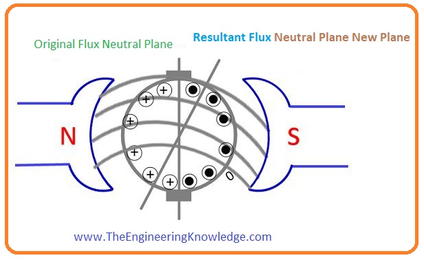
- This situation occurs when the load is connected with the machine, in this condition, there are 2 fluxes exits in the machine first one is due to the armature current that passes through the armature winding.
- The second is due to the poles of stators. The resultant flux of these 2fluxes is denoted as in the given figure.
- When the flux of stator poles interacts with then it distorts this flux.
- This distortion in the armature flux increases the strength of flux in the upper part of the North Pole and lower portion of S- pole.
- Like this flux, strength reduces at the lower portion of the N-pole and upper portion of S-pole.
- The resulting flux produced in the generator is moved to the generator rotation direction.
- As M.N.A is at 900 to the resultant flux axis. So its position varies with the resulting flux.
Effect of Armature Reaction
- These are some effects that occur due to the armature reaction.
- As we discussed above that armature reaction decreases flux strength flux at one half of the pole and decreases at the second half.
- So the resulting flux is also less that decreasing the output voltage.
- This effect is also called the demagnetizing effect as flux is reduced due to armature reaction.
- The resulting flux is distorting. Due to this the direction of M.N.A changing toward the rotation direction of the generator while in the motor it is opposite in motor.
How To Reduce Armature Reaction?
- There are two methods to decrease the armature reaction in dc machines.
- Compensating winding
- Interpol
Compensating winding:
- As we know that armature is caused by the flux of armature winding that is produced by the current passing through this winding.
- If we connect another winding with the armature winding in series then the armature current also passed through this winding. This separate winding is known as compensating winding.
- The current passing through compensating wining is opposite in polarity to the armature wining flux so both of these fluxes cancel the effect of each other.
- So armature reaction can be minimized by this method.
Interpol
- To the reduction of armature reaction, there is another method in which small poles called interpoles are placed among the main poles of stators.
- The winding of these poles is connected with the in series of armature winding, armature current passes through that winding and creates flux.
- These two fluxes of armature windings and interpoles cancel each other due to opposite polarity so it reduces the armature reaction.
FAQs
What is the armature reaction, and how can it be reduced?
- The armature reaction resulted in distortion in the main field flux. That reduces if the reluctance of the path of the cross-magnetizing field increases. The armature teeth and air gap at the pole tip provide reluctance for armature flux.
What is the difference between an armature and a commutator?
- The armature core works as an iron conductor in a magnetic field, and as a result, laminated avoids eddy current flow. The commutator exists at the end of the armature and comes with a wedge-like part of hard-drawn copper and insulation made with thin sheets of mica.
What are GNA and MNA in armature reaction?
- The geometrical neutral axis is an axis that bisects the angle between the center line of adjacent poles. The MNA is an axis made at 90 degrees to the mean direction of flux passing through the armature center.
That is the detailed post on the armature reaction I have explained this tutorial with the detailed. If you have any query ask in comments.Thanks for reading. See you in the next tutorial.
Hello there! I know this is kinda off topic nevertheless I’d figured I’d ask.
Would you be interested in trading links or maybe guest writing a blog post or vice-versa?
My blog addresses a lot of the same topics as yours and I feel we
could greatly benefit from each other. If you might be interested
feel free to send me an email. I look forward to hearing from you!
Fantastic blog by the way!
No matter if some one searches for his necessary thing, therefore he/she wants to be available that in detail, therefore that thing is
maintained over here.
Very effectively written information. Will probably be invaluable to anyone who usess it, including myself. Keep up the good work – for positive i’ll check out extra posts.