 Hi, readers welcome to another interesting post. In this post, we will have a detailed look at 555 Timer as an Oscillator. The 555 timer is category of IC circuitry used in different electronic projects. In this post, we will discuss the use of this module as an astable or free-running multivibrator that also called square wave oscillator
In the previous tutorial, we have discussed the usage of these modules as voltage-controlled oscillators. So let’s get started with 555 Timer as Oscillator.
555 Timer as Oscillator
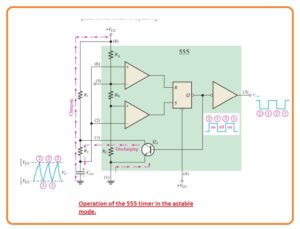
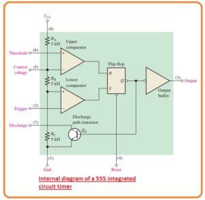
- The 555 timer comprises of 2 comparators flip flop discharge transistor and voltage divider circuitry constructed with the resistances this arrangement can be seen in the below figure.
- The flip flop or bistable multivibrator is a digital instrument that is new for you at this location.
- In short, it is 2 stable module that has an output at two levels first is high voltage denoted as s or low voltage level denoted as reset or R.
- The condition of output can be varied with the use of a suitable value of input voltage.
- The voltage divider circuitry constructed with the resistance is used to adjust the voltage comparator level.
- The resistance used has a similar value since the utmost comparator has a reference value of voltage 2/3Vcc and the lower capacitor has 1/3Vcc.
- The comparator output regulates the condition of the flip flop. If the value of trigger voltage is less than one
- The comparators’ outputs control the
state of the flip-flop. When the trigger voltage goes below 1/3Vcc the flip flop adjusts and the output goes to its larger value. - The threshold input is generally linked to exterior RC timing circuitry. When the exterior capacitor voltage is larger than the 2/3Vcc the upper comparator adjusts the flip flop that is with the output again its less value level.
- When the output has less value the discharge transistor gets on to deliver the path for fast discharging of the exterior timing capacitor.
- This normal working permits the timer to arranged to the exterior elements as an oscillator.
Astable Function
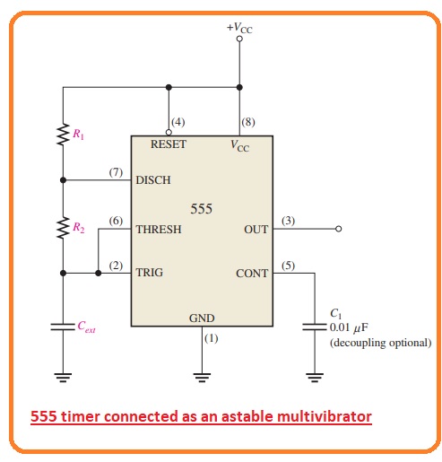
- The 555 timers linked to the function in the astable feature as a free-running relaxation oscillator can be seen in the below figure.
- Note that the threshold input is linked with the trigger input. The exterior elements R1, R2, and Cext make the timing circuitry which adjusts the frequency of oscillation.
- The capacitor having a capacitance of 0.01uF linked with the control input is used for decoupling and no effect at the working.
- At start when eh power is on the capacitor is not charged and so the trigger voltage or pin 2 has zero vol.
- It causes the lower comparator to become high and the output of the upper comparator is low causes the output of the flip flop and so the base of low and causes the transistor in the off state.
- Now starts the charging and it can be seen in below figure.
- When the capacitor voltage becomes 1/3Vcc the lower comparator moves to its low output condition and when the capacitor voltage becomes 2/3 Vcc the upper comparator move to the high output condition.
- This process resets the flip flop and causes the base of Qd to become high and it on the transistor.
- This series makes a discharging way for the capacitor transistor.
- Now the capacitor get started to discharge which causes the upper comparator to become high adjusting the flip flop that creates the base of less and off the transistor.
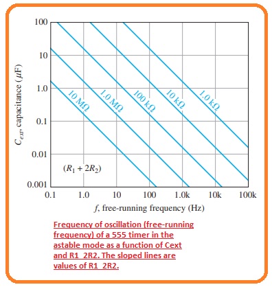
- The value of the oscillation of frequency is given in the below figure and can be calculated with the use of graph given below.
Working of 555 Timer as a Voltage-Controlled Oscillator (VCO)
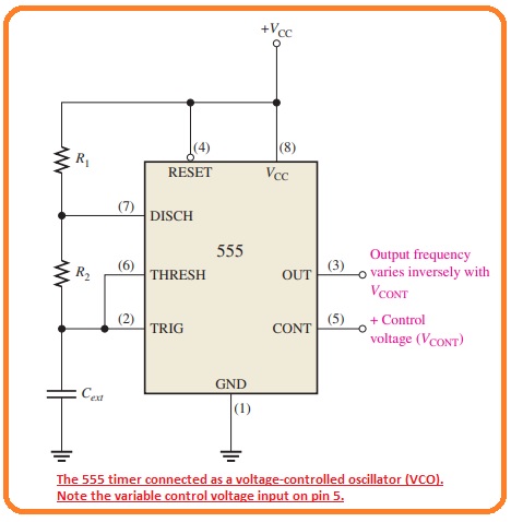
- The 555 timers can be adjusted to work as VCO with the use of similar exterior links for astable working with that variable control voltage is given at the cont input can be seen in the below figure.
- As can be seen in the below figure the control voltage varies the threshold values of 1/3Vcc and 2/3Vcc for the inner comparator.
- With the value of control voltage, the upper value is Vcont and the lower is 1/2Vcont we can observe the inner circuit of 555 timers.
- When the control voltage varied the output frequency also changes.
- The increment in Vcont causes the increment in charging and discharging time of the outer capacitor and causes the frequency to reduce.
- The decrement Vcont reduces the charging and discharging time of the capacitor and causes the frequency to rises.
- The common application of the VCO is in phase looked that is used in numerous categories of communication receivers to detect changes in the frequency of the applied signal.
That is a detailed post about 555 Timer as an Oscillator if you have any further queries ask in the comments. Thanks for reading. Have a nice day.


