 Hello friends I hope you all are doing great. In this post, we will have a detailed look at Operation of Relaxation Oscillators. This category of oscillator is used in RC timing circuitry and such modules which varies their conditions to produce a periodic signal.
In this post, we will discuss their circuit working operational and some other related parameters. So lets’ get started with the Operation of Relaxation Oscillators.
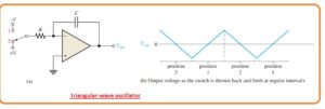
What is Triangular-Wave Oscillator
- The operational amplifier integrator also used as basic circuitry for the triangular wave oscillator.
- The basic structure is discussed in the below figure here a dual polarity input switch is operated.
- The usage of switch is for only understanding in practical this switch is linked.
- When the state of the switch is one then the negative voltage is given and the output is positive.
- When the switch has the second position a negative-going ramp is generated.
- If the state of position is varied from second to first at regular intervals the output of triangular shape is generated as can be seen in the above figure shown b.
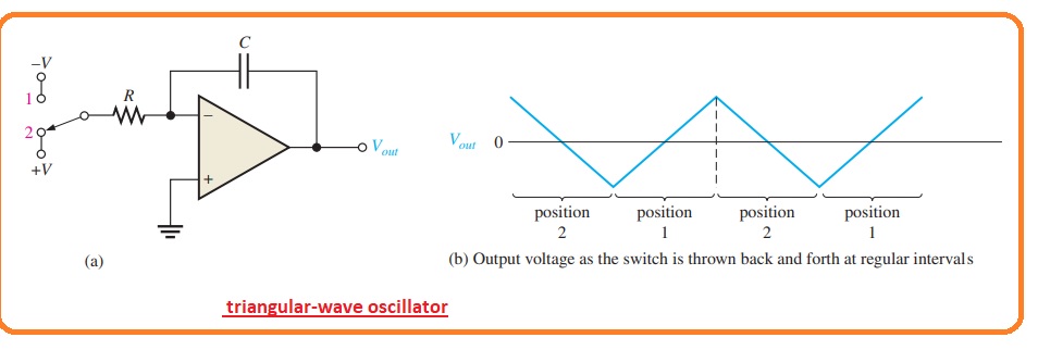
Practical Triangular-Wave Oscillator Operation
- In a practical triangular wave oscillator their an operational comparator having hysteresis to do the switching operation as can be seen in the below figure.

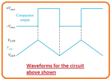
- The function is described here. For starting suppose that the output voltage of the comparator is at an extremely negative point.
- This result is linked to the inverting terminal of the integrator through generating a positive cycle at the output terminal of the integrator.
- When this cycle gets the UTP or upper trigger point the comparators change its state to the extreme positive level.
- The positive level helps the integrator cycle or a ramp to varies its direction in negative.
- This ram changes its position to the point of LTP or lower trigger point to the comparator.
- At this location, the output gets switched to the extreme negative level and this cycle continues to repeat.
- This process can be seen in the below figure.
- As the comparator generates the square wave output the circuitry shown in the above figure can be used in two ways as a triangular wave oscillator and square wave oscillator.
- This category of modules is called a function producer since they generate output value larger than one.
- The results amplitude of the square wave is adjusted with the output variation of the comparator and resistance and adjusts the amplitude of the triangular output with the creation of UTP and LTP.
VUTP = +Vmax(R3/R2)
VLTP = -Vmax(R3/R2)
- Heere the comparator output point -Vmax and +Vmax, has similar value.
- The frequency of these two signals relies at the R1C time constant with that amplitude setting resistance and resistance R2 and R3.
- With the change in the value of resistance R1, the frequency oscillation can be changed without varying the output amplitude.
fr=1/4R1C (R2/R3)
Sawtooth Voltage-Controlled Oscillator (VCO)
- The VCO or voltage controlled oscillator is a type of relation oscillator that has frequency changeable with the change in dc control voltage.
- VCO can generate either sinewave or no sinewave.
- There is one technique to create a sawtooth VCO is through the operation amplifier integrator which used switching modules or PUT in parallel link to the feedback capacitor to eliminate every ramp at the respective level and reset the circuitry.
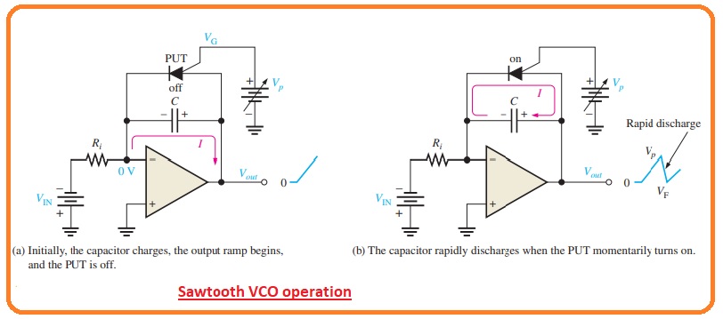
- The PUT is a programmable unijunction transistor having anode-cathode and gate terminal.
- The gate is biased in a positive way according to the cathode. When the anode voltage larger than the gate voltage through the value of 0.7 volts the PUT changes state to on and operate in forward biased state.
- When eh anode voltage is less than this point the PUT becomes off. With that, the current should be larger than the holding value to sustain the conduction.
- The working of the sawtooth VCO starts when the negative dc input voltage generates a positive cycle at the output point.
- When the ramp is rising the circuitry operates like a regular integrator. The PUT triggers on when the output cycle raises the gate voltage witha value of 0.7 volts.
- The gate is adjusted to the almost required sawtooth extreme voltage.
- When the PUT gets on the capacitor gets discharged can be seen in the figure denoted as b.
- The capacitor does not get discharged completely to 0 since the PUT has a forward voltage.
- Discharge continues till the PUT current has value less than the holding value.
- At this location, PUT gets off and the capacitor starts to get charging which produces a new output cycle.
- The cycle repeats continuously and causes the output is a sawtooth signal.
FAQS
How do relaxation oscillators work?
- The circuit comes with a feedback loop having switching devices like a transistor, comparator, operational amplifiers, or negative resistance components such as a tunnel diode, repetitively charged capacitor, or inductor with resistance until gets the threshold level for discharge again.
What is the operation of the UJT relaxation oscillator?
- UJT relaxation oscillator comes with a UJT circuit where the emitter is connected with a resistor and capacitor. The timing of output signals is defined with use of the RC time constant. The supply voltage is given to the circuit and the capacitor starts charging through a resistor.
What is the basic operation of oscillator?
- There are different types of electronic oscillators but all work on the same features, the oscillator uses a sensitive amplifier whose output is given back to the input in phase. So signal reproduces and retains that called positive feedback.
That is all about the Operation of Relaxation Oscillators if you have any further queries ask in the comments. thanks for reading.