 Hi, friends welcome to another interesting post. In this post, we will have a detailed look at the Operation of RC Feedback Oscillators. There are generally 3 categories of feedback oscillators that uses RC circuitry to generate sinusoidal results which called Wien bridge oscillator second one is phase shift oscillator and the third one is twin T oscillators.
Normally RC feedback oscillator is used for the frequency range of one megahertz. But Wien bridge is the most commonly used Rc oscillator circuit. In this post, we will discuss circuits operation and some other related parameters. So let’s get started with Operation of RC Feedback Oscillators.
Wien-Bridge Oscillator
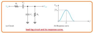
- There is one category of sensual generate feedback oscillator isWien bridge oscillator. The main part of this circuitry is lead-lag circuitry which can be seen in the below figure.
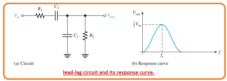
- The resistance R1 and CapacitorC1 make the lag part of the circuitry and resistances R2 and capacitroC2 make the leading part of the circuitry.
- The working of this lead-lag circuit is described here. At less value of frequency, the lead circuitry operates due to the large value of reactance of capacitor C2.
- With the increment in frequency and decrement in this frequency causes the output voltages to increased.
- At a certain value of frequency, the response of lag circuitry dominates and reduces the value of XC1 that causes the output voltage to decrease.
- The resultant curvature for the lead-lag circuitry can be seen in the above figure denoted as b. THis circuitry denotes that the output voltage extreme at the frequency known as the resonant frequency.
- At this location, the attenuation (Vout/Vin) of circuitry is 1/3 if R1 = R2 and XC1 = XC2 as described the respected expression.
Vout/Vin=1/3
- The mathematical expression of the resonant frequency is
fr=1/2πRC
- For an explanation, the lead-lag circuitry in the Wien bridge oscillator has the resonant frequency for which phase shift in the circuitry is zero degrees and the attenuation value is1/3.
- A value less than Fr the lead circuitry dominated and the output lead the input.
- Over the value of fr lag circuitry dominated and output lags behind the input.
Basic Circuit Configuration
- The leading and lagging circuitry is used in the positive feedback loop of the operational amplifier as can be seen in the below figure.
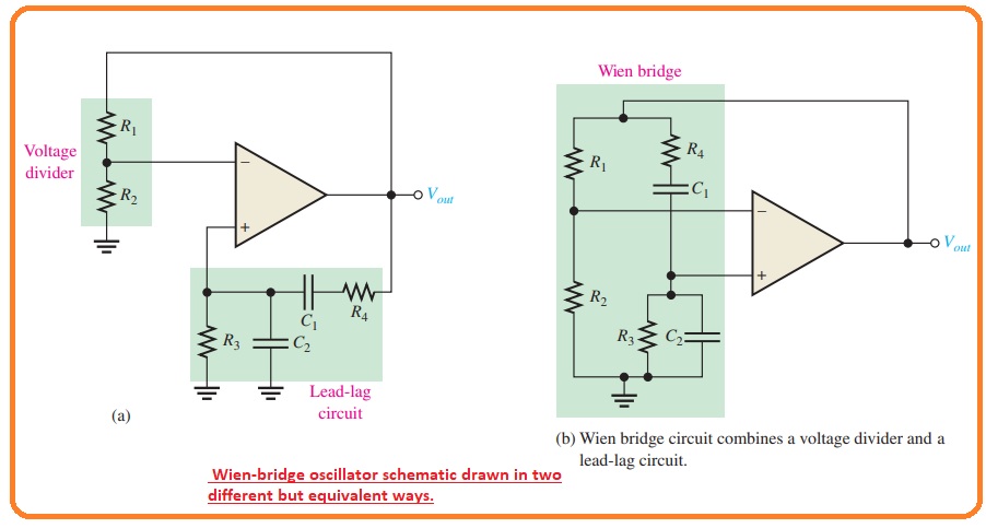
- The voltage divider circuitry is used in the negative feedback loop.
- The Wien bridge oscillator circuitry can be seen like a non-inverting amplifier arrangement with the input signal sent back to the output by the lead-lag circuitry.
Acl = 1/B =1/R2/(R1 + R2)
- The circuitry is rearranged in the figure denoted as b indicate the operational amplifier is linked with the bridge circuitry.
- one limb of the bridge is lead-lag the circuitry and the other is in voltage divider configuration.
Positive Feedback Requirements for Oscillation
- As we know that the circuitry to generate a sinewave result the phase shift about the positive feedback loop should be zero degrees and the gain about the loop should be one.
- The zero degrees phase shift requirements is followed when the value of frequency is fr since the phase shift in the lead-lag circuitry is zero and there is no inversion from the non-inverting input of the operational amplifier.It can be seen in the below figure.
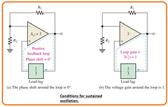
- The unity gain requirements followed in the feedback loop when
Acl = 3
- This offsets the 1/3 attenuation of the lead-lag circuitry to make the net gain about the feedback loop equal to one as shown in above figrue denoted as b.
- To get a closed-loop of the gain value of three.
R1 = 2R2
Acl = (R1 + R2)/R2=(2R2 + R2)/R2
Phase-Shift Oscillator
- The below figure denoted that the sinewave feedback oscillator known as the phase shift oscillator.
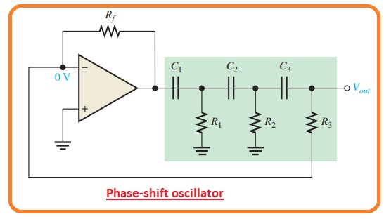
- Every of 3 RC circuitry in the feedback loop can be offered an extreme phase shifting close to ninety degrees.
- Oscillation exists at the frequency where the net phase shift in the 3 RC circuitry is one eighty degrees.
- The inversion of the operational amplifier offers the extra one-eighty degrees to fulfill the need of oscillation of three sixty degrees.
- The attenuation of3 section Rc feedback circuitry is given here.
B=1/29
Twin-T Oscillator
- It called twin T since the 2 T type Rc filters used in the feedback loop as can be seen in the below figure.
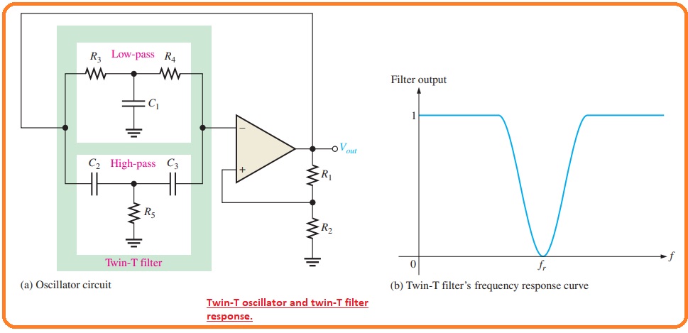
- On twin, T filter configuration comprises of less pass response and the other comprises of the high pass response.
- The combined parallel filter comprises of low pass response and the other comprises of high pass response.
- The combined parallel filter generates a band stop or notch response having a center frequency equal to the required frequency of oscillation as can be seen in the above figure
- Oscillation can not exist at a frequency over or less of fr since the negative feedback is passing in the filters.
- For fr there is very less negative feedback in the positive feedback in the voltage divider permits the circuitry to get oscillate.
That is a detailed post about the Operation of RC Feedback Oscillators if you have any further queries ask in the comments. Thanks for reading.