
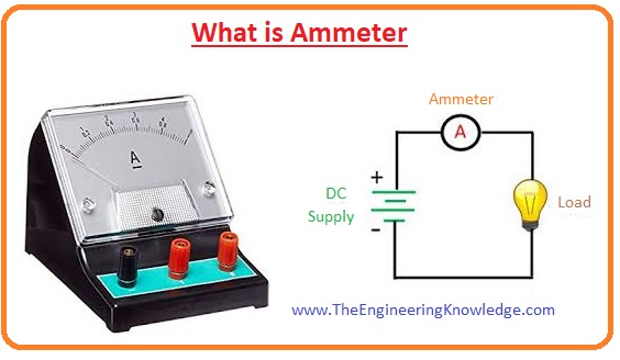
Hello, friends, I hope all of you are having fun in your life. In today’s tutorial, we will explain what an ammeter is. In 1820 Hans Christian Ørsted, who belonged to Denmark, discovered the relationship between current, magnetic field and physical forces (gravitation, electromagnetism, weak interaction, and strong interaction). He performed an experiment for this relationship; he saw that the needle of the compass moved towards north when current flowed in near the wire. For current measurement, he used a tangent galvanometer.
In electrical and electronic engineering, there are numerous metres used, like a voltmeter for voltage measurement and an ohmmeter for resistance measurement. In today’s post, we will have a look at the ammeter, its working, construction, applications and some other related parameters. So let’s get started with what an ammeter is.
What is an ammeter?
The ammeter is also known as the ampere meter and is used for the measurement of electric current, and the unit of the current measured by this meter is the ampere, so it is also called the ampere meter.
The ampere meters used to find the small value of currents like mass; the ammeter used before the 19th century was only used in different laboratories since their working operation depends on the magnetic field of the earth.
After the nineteenth century, some improvements were made in these meters, and now they can be used at any location with higher accuracy.
The difference between an ammeter and a galvanometer
Now we compare an ammeter and a galvanometer and will observe what the difference is between these two meters.
A galvanometer is used to find a very small amount of current passing through the circuit, and an ammeter is used to find a larger current in amperes.
For the working of a galvanometer, there is a need of a magnetic field, and in an ammeter, there is no need of a magnetic field.
The accuracy of the galvanometer is larger than the ammeter, and the ammeter is less accurate.
Due to its higher accuracy, galvanometers can find a small amount of variation in current.
A galvanometer can be used only for direct current measurement, while an ammeter can be used for both direct current and alternating current measurements.
A galvanometer is used in bridge circuits for the measurement of current, and an ammeter is used in electrical circuits.
A galvanometer is a mechanical instrument, while the ammeter is both electric and mechanical.
| Features | Ammeter | Galvanometer |
|---|---|---|
| Definition | The ammeter is a measuring instrument used to measure current in a circuit | This meter is used to detect the strength and direction of the electric current in a circuit. |
| Measuring quantities | It measures current | It measures the magnitude and direction of the current in the circuit. |
| Zero position | It has a zero position on the left scale. | It has zero position on the middle of the scale. |
| type | it is (an analog ammeter) or an electronic device (digital ammeter). | Electromechanical device. |
| The type of current measured | It measures direct current (DC) and alternating current (AC). | Only direct current (DC). |
| Presence of a magnetic field | It can work with or without the existence of a magnetic field. | magnetic field is needed for the working of the galvanometer. |
| Accuracy | High | less accurate. |
| Sensitivity is | less sensitive device. | High |
| Substitution | An ammeter is not used in place of the galvanometer. | A galvanometer used as an ammeter connected a small resistance in parallel with it. |
| Used as a voltmeter | No. | Yes can be used with the use of high-value resistance in series to galvanometer, |
| Applications | It used for current measuring | Galvanometer used in bridge circuits and potentiometer for the detection of zero current. |

Difference between an ammeter and a voltmeter
Ammeter:
- It used for the measurement of current.
- Its resistance value is less as compared to the voltmeter.
- In a circuit, it is connected in series.
- This meter is more accurate than the voltmeter.
- Its range can not be varied.
Voltmeter:
- It is used to find the value of voltage in any circuit.
- Its resistance value is high than that of the ammeter.
- It is connected in parallel in the circuit for voltage measurement.
- Its accuracy is less than the ammeter.
- Its range can be varied.
| Ammeter | Voltmeter |
| Measure current | Measures voltage over two points |
| It has less resistance | High resistance. |
| In series combination connection | Parallel connection |
| Its range not change | Range changes |
| Ideal ammeter: resistance is 0. | F ideal voltmeter, infinity resistance |
| Denoted with A. | It is V symbol |
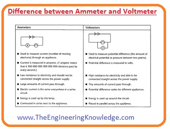
Why is an ammeter connected in series and a voltmeter in parallel in a circuit?
The ammeter is used to find the value of current in a circuit. For accurate measurement of current; it should pass through the ammeter.
So it arranges in series in a circuit. If we place it in parallel and its resistance is also less, so all current will flow through it and can damage this metre because we know that current always follows the least resistance path.
So it is always preferred to connect in series for current measurements.
While the resistance of the voltmeter is high, if we place it in series, then there will be less amount of current flowing through the circuit. Due to this, it is used in parallel to measure the voltage across any element.
How to use an ammeter
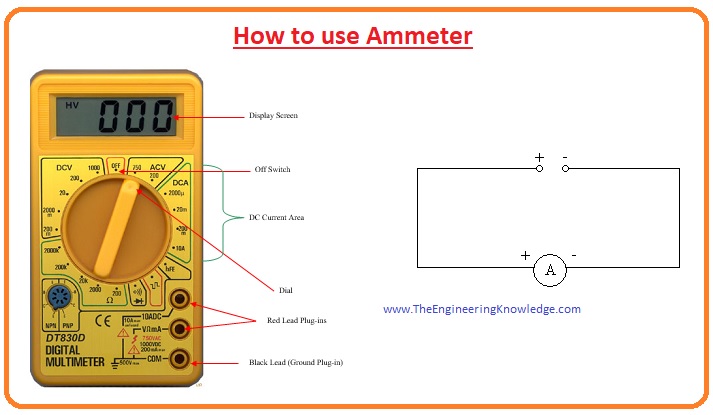
There are some steps you must follow to use an ammeter; all these steps are mentioned here in detail.
For current measurement, we discussed it should be connected in series. First of all, you should create your circuit for which you have to use an ammeter.
Break the circuit where you want to measure current; for this, remove the wire at your desired location.
Then attach the red lead of the ammeter to the positive terminal and the black lead to the grounded terminal of the ammeter.
After that, place the ammeter in a circuit for which you are going to measure the current. The positive red lead of the meter should be attached to the positive terminal of a battery.
and connect the black lead to the point that is close to the negative terminal of the battery. If these connections are not right, then the meter can be damaged.
Types of ammeter
- now we discuss the types of ammeters that are listed here in detail.
- moving coil ammeter
- digital ammeter
- electrodynamic ammeter
- hotwire ammeter
- integrating ammeter
- moving iron ammeter
- moving magnet ammeter
Moving coil ammeter
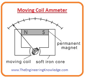
This meter is also called a d’Arsonval galvanometer, or we can say the d’Arsonval galvanometer is known as a moving coil ammeter.
It measures the current through magnetic deflection. This meter has a coil; when current passes through that coil, it rotates in a magnetic field.
The currently used ammeter is designed by Edward Weston and has 2 spiral springs for restoring force.
The gap between the core of the iron and the permanent magnet poles allows the movement of a meter needle directly proportional to the current.
The scale of this meter is linear. This meter has the ability to measure both direct and alternating current.
The coil of this meter moves between the permanent magnet poles. When the current flows through the coil, it moves in between poles of the magnet.
The movement or deflection is directly proportional to the current flowing through the meter or coil.
Moving magnet ammeter
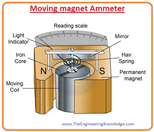
- This is also used to measure the value of both dc and AC currents. This meter consists of a coil that is placed among the poles of a permanent magnet.
- After the movement of current through the coil, it shows some variation in its position. The variation in coil position is directly proportional to the current flowing through the meter.
Electrodynamic ammeter
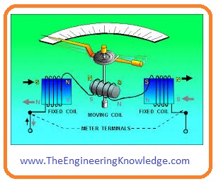
- It can also find the value of alternating and direct current passing through the circuit.
- Its accuracy is larger than the moving coil meter and permanent magnet ammeter.
- its main feature is that there is no need of separate calibration for both ac and dc measurements.
Moving iron ammeter
This meter used an iron piece that shows some deflection when a force is exerted on this iron by the fixed coil wire.
This meter was first manufactured by Friedrich Drexler in 1884, who was an engineer of Austria.
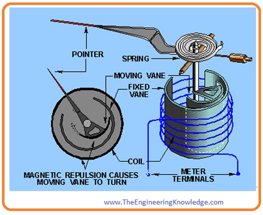
This meter has the ability to measure both direct and alternating current accurately. The iron piece of this meter comprises the moving vane connected with the pointer and the second vane that is fixed, and a coil surrounds these vanes.
When either direct current or alternating current flows through the coil, it induces a field in both fields, the fixed and the moving vane. The direction of the field is opposite to each other, so these vanes repel one another.
The moving vane moves opposite to the force applied by the helical spring, and the deflection in the moving iron meter is directly proportional to the square of the current.
Ammeter shunt
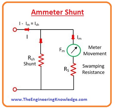
- When a high value of current flows through the ammeter, it can cause serious problems for a meter to avoid such problems, a resistance is connected in parallel to the ammeter this resistance is known as an ammeter shunt.
- If a certain current flows through the circuit, then most part of the current will flow through the shunt resistance and will not damage the meter.
Effect of Temperature on Ammeter
The ammeter is a sensitive instrument that can get affected by the environmental temperature. The alteration in temperature value also varies the measured value of current or readings.
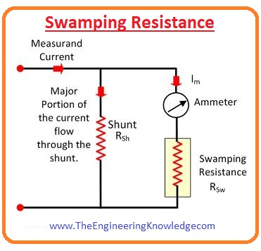
The effect of temperature can be minimized by using the resistance called swamping resistance and having a zero value of temperature coefficient.
In-circuit, it is attached in series with the ammeter.
Read also:
- What Does an Anemometer Measure, Types & Work Process
- What is a Digital Voltmeter – Types, Working, Uses, Symbol and Applications
- What is a potentiometer – Construction, Types, Uses, Working Principle & Applications
- Difference Between Colorimeter and Spectrophotometer
- Difference Between Ammeter & Voltmeter
- Difference Between Galvanometer & Ammeter
- Difference Between Potentiometer & Voltmeter
Faqs
What is the construction and working of an ammeter?
The working of an ammeter is based on the magnetic effect of current; its working is that resistance and inductance must be less. The ammeter comes with a coil of wire and a fixed permanent magnet. So an ammeter cannot be connected in a parallel combination.
What is an ammeter and its types?
An ammeter is used for measuring DC or AC in amperes. The ammeter has features to measure different values of current since at high values just a small part of the current is moving through the meter. The shunt in parallel combination with the meter carries the larger part.
What is the application of an ammeter?
It is best to measure current passing in housing for electrical instruments. It is also used in manufacturing and instrumentation. An ammeter is also used with a thermocouple to check the temperature.
What are the four types of ammeters?
The ammeter is used for measuring current through circuit connections in series. There are many ammeter types, like moving-coil, electrodynamic, integrating, moving-iron, hot wire, and picoammeters
How is an ammeter constructed?
The ammeter is made with the connection of the shunt-resistant Rsh in parallel to the movement and complete configuration, movement, and shunt.
What does an ammeter work on?
An ammeter measures current with the use of a magnetic field about a coil or wire connected to a circuit. Current affects the magnetic field, and the strength of the magnetic field changes through the magnitude of the current.
Is an ammeter AC or DC?
The ammeter measures current, which means the value of current that can generate the same heating effect when produced by the current measured. So it can be used in DC as well as AC circuits.
What is the formula for an ammeter?
The formula of an ammeter is the relation between current and resistance in current given by Ohm’s law: I = V / R, here I is current, V is voltage, and R is resistance in the circuit.
What are the three uses of an ammeter?
It is used to measure current in circuits.
It is used in a circuit to check if the circuit is working or not.
It is used in industries to check device uses and circuits.
What is the construction and working principle of an ammeter?
The ammeter is connected in series with a circuit for measuring the complete current flow. The measured current and inner resistance of the ammeter are sources of power losses in devices. An ammeter circuit provides low resistance, so small voltage loss exists in the circuit.
What is the structure of an ammeter?
There is a rotor with the coil wound in the ammeter. When the current passes through the ammeter coil, the rotor will move due to the magnetic field. Higher current flow and a stronger field of the coil and rotor will be.
What is the range of an ammeter?
The range of the ammeter defines the high capacity of the current it measures. For example, if there is an ammeter that comes with a dial from zero to 300, it means can read a current of about 300 amperes. For analog meters, digital ammeters have no dial exists, and measures are on the screen according to capacity.
That is a complete post on the ammeter. I have mentioned each and everything related to the ammeter. If you have any questions about this post, ask in the comments. Thanks for reading. See you in the next tutorial.




You made various fine points there. I did a search on the subject matter and found mainly persons will go along with with your blog.
Hi there very cool web site!! Man .. Excellent .. Superb ..
I’ll bookmark your web site and take the feeds additionally?
I’m satisfied to seek out a lot of useful info here in the post, we’d like develop extra strategies in this regard, thanks for sharing