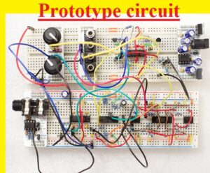
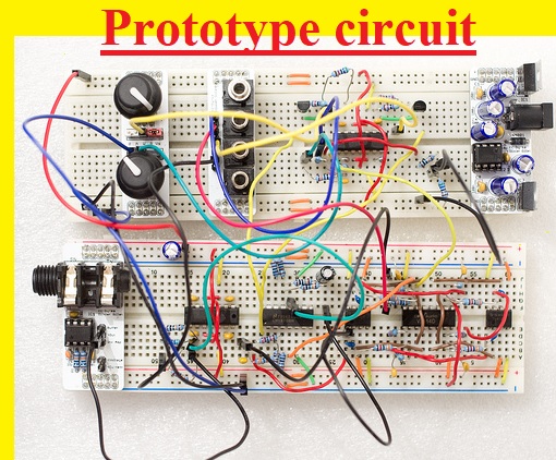
 Hello, readers welcome to the new post. Today we will discuss HOW TO MAKE PROTOTYPE ELECTRONIC CIRCUITS. The electronic prototype is a combination of hardware and software designing through the use of PCB boards that are created through the use of functional prototypes.
The prototype is basically a sample of the real project that we are going to make. In this post, we will discuss the importance of a prototype that will help us to make circuit design and configuration very accurately according to our requirements. So let’s get started
Introduction to Prototype
- The prototype is a circuit technique that is used to find the error in our design by making components connections on the breadboard but not permanent connections.
- With breadboard, there is some other types of boards like stripboard and perfboards used for the creation of the prototype. These boards also known as prototype boards
- On these boards, there are holes configured to make connections of components for circuits. You can use a soldering or non-soldering process to connect the project components on these boards.
- But before making the connection of these components on boards you must have a circuit design of your project that will help to make an accurate design.
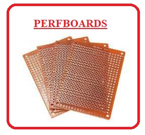
What is PERFBOARDS
- Prefbaord also known as DOT PCB used for electronic prototyping. It has a thin structure has holes on its surface that has 0.1 inches of spacing
- These boards have copper pads about their areas and some bare boards also used.
- The perfboards of fewer prices have pads on one side and high-quality perfboards have pads on both sides
- As every pad has electrical isolation and the engineer uses wire wrap or miniature point-to-point wirings.
- Different components used in electronics like diodes, transistors, and resistances are connected on the boards and have lamination like FR4, FR2, etc

Stripboard
- It generic name for mostly used electronic prototyping material used of circuit boards.
- It has 0.1 inches of regular grid holes with wide parallel trips of copper cladding,
- It is also called Veroboard. It is not used for surface mount components but components can be mounted on tracks especially if tracks are cut through small cutting devices
What is BreadBoard

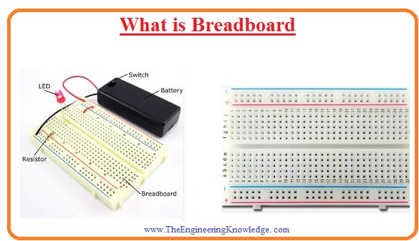
- The most common board for prototyping is a breadboard. It was as a base for the creation of electronic projects practically after testing on this board.
- It has holes like other prototyping boards and components can be placed on these holes.
- Currently used solderless breadboard socket comprises of a perforated block of plastic having many tin plated phosphor spring clips belove the perforations.
- These clips have 0.1 inches of space. It is created through use of white plastics and not soldering used for components connection
- The property of this board is that can be used again for new circuits when needed.
HOW TO USE A BREADBOARD
- To make a prototype of the circuit just place components of your circuit in the holes of the breadboard and left them there not using any soldering process.
- There are different directions mentioned on the boards to make connections according to that layout. You must note that a row of five holes has a connection electrically. Like Row, A to E are connected and F to J are connected
- Column + and – has an electrical connection that uses for power connection and ground
- These strips of vertical configuration are used for power and ground purposes known as power rails.
How to use Jumper wire in Breadboard
- Jumpers wires are very helpful to make prototypes on a breadboard. These prices are very low
- it is just like a normal wire but has a connection pinout at both ends. That helps us to link our components on the board for circuit creation
- These wires have different colors and that helps you to define the certain wire for your specific component connection
- There are three main types of jumpers female to female, male to male, and male to female.
- Normally male to male wire is used since one side easily place in the board hole and at another end, the wire can be link
breadboard Advantages
- The main advantages of the cutting board are discussed here.
- with the help of this board, we can change the connection wiring of the devices used in the circuits as per our requirement.
- This board helps us to exchange the companies used in the circuit when we needed it.
- Circuit construction on this board is a very quick and easy process due to the absence of soldering.
- Here is the main advantage over the PCB board is that we can connect an ammeter to this board at any point where we need to measure currently but these features are not there for the PCB board.
That is all about the PROTOTYPE ELECTRONIC CIRCUITS all details has explained. If you want to know more ask below comments section


