 Hello, readers welcome to the new post. Today we will discuss Introduction to LT1085. It is a type of voltage regulator that make positive adjustable low dropout linear volts. Its output current value is about three ampers and provides a high efficiency than other electronic devices. Its output volts at the input terminal are about 2.55 to thirty volts with there are different output volts that can be get.
A voltage regulator is an electronic circuit designed to automatically maintain a constant voltage. A voltage regulator can use a basic feed-forward configuration or can have negative feedback. It comes with electromechanical phenomena or electronic components. On the basis of circuit design, it may be used to regulate one or more AC or DC voltages. Electronic voltage regulators are designed for different devices such as computer power supplies where they stabilize the DC voltages used by the processor and other components. In automobile alternators and power station generator plants, voltage regulators control the output of the plant. In a power distribution system, voltage regulators may be connected at a substation. Voltage regulators have equal importance in an electronic and electric field.
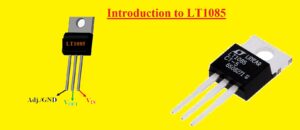
LT1085 common packagings are TO-220 and DD packaging. In this post, we will discuss its different parameters features pinout, and applications. So let’s get started Introduction to LT1085
Introduction to LT1085
- The voltage regulator LT1084 is configured to handle the load value of three ampers, 7.5 ampers, and five ampers with higher efficiency.
- Its inner circuit is created to work up to one volts input to output differential and its dropout volts are signified as a function of load current.
- It has dropout for 1.5 volts and the highest current value and for reduction of low load current.
- Through the use of onboard trimming, reference volts can be adjusted to a one percent value
- The value of the current can also be trimmed, reducing the stress on the regulator and power supply circuits facing overload conditions
- This module has compatibility with the older three pins regulators. There is just a need for ten microFarad capacitors to handle this component.
- Though it is used in different circuit designs. Contrary to PNP regulations that lose about ten percent of current as quiescent current but LT1083 quiescent current is not wasted but flows in the load and enhances the efficiency

LT1085 Features
- Here are some features of LT1085 are explained.
- It is available in three pins TO-220 packaging and DD packaging
- It comes with over-current and over-temperature protection circuits
- Its line regulation is about 0.05 percent
- The operating current is five milliamperes
- Its ripple rejection is seventy-five dB
- Its output has variable nature
- Its output current is three ampers
- Input supply for this component is 2.55V to 30V
- Low dropout volts are 1.3V for three campers
LT1085 Pinout
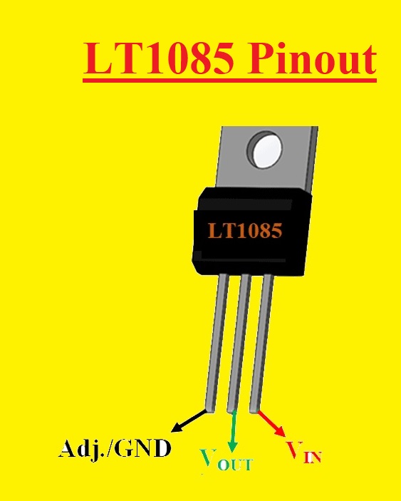
- Its pin description is given here. that are 3 in number
- GND/GND: Adjustable pin used for volts adjustment at output and Ground for ground connection
- Output: Here output volts were taken out
- Input: Input is provided
LT1085 Working
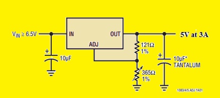
- The working operation of LT1085 is simple and needs less quantity of components for circuit creation. The pin configuration of this model is like the AZ1084.
- In the below crucial adjustable mode of this component can be seen and the value of output volts can be varied through the change of the value of resistance attached to the ADJ pin of this regulator
LT1085 in Protection Diodes Circuit
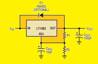
- In normal function, there is no need of a protection diode for this component. While in older regulators there is a need of a diode between the adjustment pin and output pin through the output to input to avoid the overstressing
- There is a limiter resistor used on the path of the LT1083 pin. So in the case of the capacitor at the adjustment pin, there is no need of a protection diode to make avoid short circuit damage of the device. There is no need of a diode between input and output. But if configured this diode between input and output [ins has the ability to handle the surge current of fifty to one hundred ampers
- Through with larger output capacitances, it is not easy to get these values of surge current in normal operation.
- Through the use of high output capacitors like 100uF to 5000uF and through connecting the input pin to the ground. Through the use of a crowbar circuit at the input of this component current can be produced and a diode between output and input connected
- A normal power supply cycle will not produce a current that can damage. The adjustment pin can be operated on a transient basis plus-minus 25 volts then output value.
Main Parameters of LT1085
- The basic parameters of LT1085 are discussed here
| Output Current | 3A | Dropout Voltage | 1.3V |
| Highest input current | 30V | Max Operating Temperature | 150C |
| Highest output volts | 28.5V | Min Current Limit | 3.2A |
| Minimum input volts | 2.55V | Min Operating Temperature | -40C |
| Min output volts | 1.25 | Number of Outputs | 1 |
| Regulators | 1 | Operating Supply Current | 5mA |
| Packaging | Bulk | Polarity | Positive |
| Power Dissipation | 30W | Power Supply Rejection Ratio | 75dB |
| Output volts | 28.5 |
Applications of LT1085
- These are the main applications of LT1085
- It is used in RISC, embedded processors, and Personal computers circuits
- The supply of microprocessors consists of this regulator
- It used in battery charger
- Used in liner regulators
- Used in switching supply circuits
That is all about the LT1085 all details have been explained if you have any queries ask in the comments. Thanks for reading have a good day.


