Hi friends, in this post, we will learn What are S-Parameters? Concept, Theory, and Applications. In electrical engineering and radio frequency systems, S parameters are important. These parameters are good for understanding and optimization of complicated circuits. In this post, we will study S-parameters’ concepts, uses, and applications. So let’s get started with What are S-Parameters.
Understanding S-Parameters
Scattering parameters also called S-parameters define the component in the math matrix that defines the working of an electrical network or circuit when stimulated with signal
For high frequency, it is not easy to find voltage value and curent. S parameters define the input-output relation of the power signal between the port of the electrical network.
Electrical engineers can use S parameters for different types of engineering designs such as communication systems, ICs, and PCB board radio frequency (RF) circuits.
Components of S-Parameters
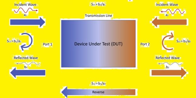
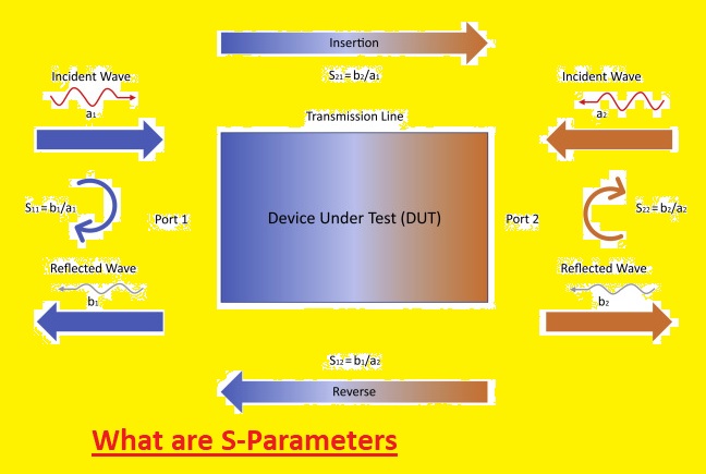
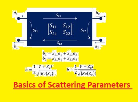
The components of S-parameters are:
- 11 = input port reflection
- S12 = reverse gain
- S21 = forward gain
- S22 = output port reflection
Applications of S-parameters
The mathematical equation helps to define different parameters. In small signal electrical circuits, linear equations are related to independent quantities of voltage and current for dependent values.
Complicated circuits can be reduced to simple black boxes, where output voltages and currents are related to input voltages and currents through mathematical relationships.
Before looking at high-frequency circuits, Y and Z parameters are the main techniques for featuring network operation. But high frequency difficult to relate network working to voltage and current for networking that cooperating transmission lines.
So S parameters define components of the scattering matrix and define scattering features of a voltage wave moving through an electrical network or circuit.
What are Traveling Waves?
When a traveling electromagnetic wave meets an obstruction or crosses a dissimilar dielectric medium, it is said to “scatter.” Thus, S-parameters describe how currents and voltages propagating along a transmission line are “scattered” as they meet a discontinuity formed by a component or a network. This discontinuity stems from a mismatch between the component or network’s impedance and the line’s characteristic impedance (or load impedance).
As an incident signal arrives at a network port, some of its energy is reflected back away from the port, while the rest is transmitted (or scattered) to the other ports in the network, resulting in amplification or attenuation of the signal.
Calculating S-parameters
As S parameters define features of incident and reflected and reflected wave at some frequencies, engineers should define frequencies with featues of impedances of devices for test
S parameters are best in the design, analysis, and optimization of microwaves and radio frequency circuits (300 MHz – 300 Ghz).
It removes the use of modeling an RF device’s inner features and helps to focus on input-output features.
Engineers operate S parameters by measuring voltage and curent at the circuit port. These parameters do not have dimension coefficients measured as voltage ratio of incident and transmitted waves.
The scattering matrix of a multiport network comes n^{2} S-parameters and each parameter denotes the input-output path of the circuit.
Every parameter dimensionless complicated number has a real component denoting signal amplitude and an imaginary part denoting the phase of signal, at the test frequency. The amplitude can be defined in linear or logarithmic scale.
Follow these features for measuring S-parameters:
- test frequency
- characteristic impedance
- allocation of port numbers
- bias current, temperature, and control voltage
Faqs
What are the S and R parameters?
R parameters define data obtained from 2 dimension profile and S parameters define data measured on the area of the surface. For the latter point use areal then of 3-dimensional” data for differentiating surface measurement from dimensional CAD and CMM type measurements.
What is S11 and S12?
S11 is the reflection coefficient at the input and is related to return loss.S12 – A transmission coefficient defines reverse gain
- S11 is equal to the ratio of reflected wave and incident wave with Zl=Zo. So S11 can drawn on an Smith chart and the input impedance of two-port devices can be measured instantly. S22 = b2/a2 for a1 = 0 or Zs = Zo.
What are S11 and S21 parameters?
- S11 measures wave reflected through impedance discontinuity in the transmission channel and S21 S21 measures the insertion loss.
What is S11 called?
(S11) reflection coefficient quantity that defines wave is reflected with impedance discontinuity in the channel of transmission. it also defined as the ratio of the amplitude of the reflected wave to the incident wave. S11 measurements in VNA.
What is S22 parameters?
S22 is the output port voltage reflection coefficient. The S parameter matrix is used for finding reflection coefficients and transmission gains from both sides of the two-port network. This feature is used for finding s-parameters of a multi-port network.
What is the difference between S11 and VSWR?
Parameters VSWR measures numerically define how antenna impedance is matched to the ratio or transmission line connected. The reflection coefficient is called s11 or return loss
What is the difference between S21 and S11 measurements?
For a simple two-part network, S11 denoted input complicated reflection coefficient or impedance of DUT, and S21 denoted forward complex transmission coefficient.
- Scattering parameters or S11 is the ratio of Reflected power (Pr) to Incident power (Pi). So Scattering parameter or S11 is negative quantity S11 (dB)= 10log(Pr/ Pi). S11 is power returned at port 1 for a given power input at port 1
Why is voltage 11kV?
The main cause is that there is a need to get 10,20,30,60,120 kV etc at the receiving point.
There can be some voltage losses due to resistance in transmission lines. For getting voltage at receiving points provdies 10% extra voltage at the sending end.
Is 11kV a voltage line?
Yes, 11kV is a voltage line. It high voltage line that is used for delivering current to long distances. 11KV lines are made with aluminum or steel cables, and insulated with a dielectric material.
.


