 Hello, friends welcome to the new post. In this post, we will have a detailed look at DC-TO-DC POWER CONTROL CHOPPERS. The chopper circuitry also called DC dc converts like the transformer of AC circuitry choppers employed to step up and step down the dc power.
They vary fixed dc power from changeable dc power. In this post, we will cover its working applications and some other related factors. So let’s get started with DC-TO-DC POWER CONTROL CHOPPERS.
DC-TO-DC POWER CONTROL CHOPPERS
- In some cases, it is required to change the voltage existing through dc source given to the load.
- The circuitry that changes the voltage of the dc supply is known as dc to dc converters or choppers. In the chopper circuitry, the input voltage has a constant dc voltage supply and output voltage changed through the fraction of time in which the dc source is linked to the load.
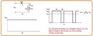
- The diagram below indicates some principle of chopper circuitry.
- When the SCR gets triggered it gets on and power is provided at the load. When it’s off the dc supply is removed through the load.
- In the circuitry shown above figure, the load is resistance, and voltage at the load is either VDC or zero.
- As the current in the load is VDC/R or zero. It is certain that smoother the load voltage and current through addition of the series inductor to filtering some of the ac elements in the signal.
- The below figure indicates the chopper circuitry having an inductive filter. The current moving through the inductor rises exertional way when the SCR is on state and reduces in the expositional way when the SCR is in the off state.
- If the inductor is high the time constant of current varies will be retained comparative to on or off a cycle of the SCR and load voltage and current will has a constant value at a certain average point.
- In the condition of the AC phase controllers, the SCR gets off at the end of every half cycle when the current move to 0.
- FOr dc circuitry there is no endpoint over which the current naturally decreases at the endpoint of the pulse. It is compulsory to use a reverse voltage it for a small time interval.
- The reverse voltage halts the current movement and gets of the SCR. When it is off it will not on till a new pulse signal is applied at the gate terminal of SCR.
- The procedure of forcing the SCR to gets on at the required time is called forced commutation.
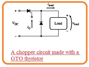
- GTO thyristors are used for chopper circuitry because they are self commutating. In contrary to SCR GTO can get off through negative current pulse provided to the gates.
- So additional circuitry required in SCR chopper circuitry to off the SCR can be removed through GTO thyristor chopper circuitry.
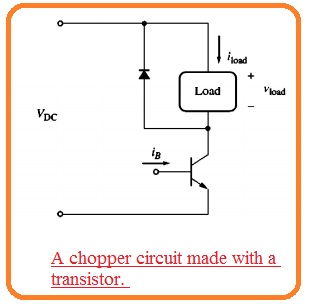
- Power transistor also self-commutating and used chopper circuitry which relies in the required power limits.
- Chopper circuitry is used with the DC power network to change the speed of dc motors.
- Their maximum benefit for dc speed control related to traditional techniques is that they are more effective than the network.
Forced Commutation in Chopper Circuits
- When the SCRs are used in choppers circuitry the forced commutation circuitry should be added to gets off the SCR at the required time.
- Mostly this category of forced commutation circuitry relies at their turnoff voltage at capacitor in a charged state.
2 main types of capacitor commutation are overlooked here. - Series-capacitor commutation circuits
- Parallel-capacitor commutation circuits
Series-Capacitor Commutation Circuits
- The below figure indicates the basic dc chopper circuitry having series capacitor commutation. It comprises of SCR the capacitor load and in series combination to one another.
- The capacitor consists of shunt discharging resistance about ti and load consists of freewheeling diode about it.
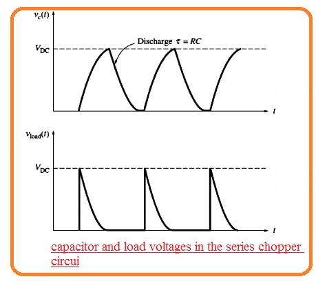
- The SCR is started gets on through the pulse provided to the gate. When the SCR gets on the voltage is provided to the load and current initiate passing from it.
- This current moves from the series capacitor at the method to load and the capacitor gets charge slowly.
- When the capacitor voltage close to VOC the current from the SCR loss to IH and SCR gets off.
- When the capacitor gets off the SCR then it gets discharge very slowly from the resistance.
- When it is completely discharged the SCR will do the fired through another pulse at gate terminal.
- The voltage and current signal for this circuitry can be seen here.
- in some cases, this category of circuitry is restricted to the duty cycle because the SCR cannot be fired again till the capacitor is discharged.
- The discharged time relies at the time constant T=RC and C should be made larger in sequence to get a high value of current passing to the load so its off the SCR.
- Resistance R should be high because the current leaking through the resistance to be decrease than the IH of SCR.
- these 2 factors if jointly used indicates that the SCR cannot be refired very rapidly after getting off. It take a long recovery time interval.
- The well equipped series capacitor commutation circuitry having a short time recovery time is can be seen here
- the circuitry is like to the above mentioned with different that the resistance is substituted with an inductor and SCR in series combination.
- If SCR is fired current will move to the load and the capacitor will become charge cut off the SCR1.
- When it is cut foo SCR2 will be fired discharge the capacitor very fastly than the resistance.
- The inductor in series combination to SCR1 saves SCR1 from instantaneous current surges which exceed the ratings.
- When the capacitor is discharged SCR2 is off and SCR1 is ready to fire again.
Parallel-Capacitor Commutation Circuits
- The second category to get forced commutation is through a parallel capacitor computation network.
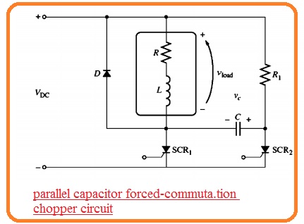
- The basic instance of the network shown in below figure.
- In this structure, the SCR1 is the chief SCR giving power to the load and SCR2 regulates the function of the computation capacitor.
- To provide power to the load SCR1 is fired. If it occurs the current passing from the SCR to load providing power to it.
- With that, the capacitor C gets a charge from resistance R to voltage equal to the supply voltage VDC.
- If time is exist of off the power at the load. SCR2 is fired when this SCR1 is gets fired the voltage about the loss to 0.
- Because the voltage about the capacitor cannot vary an instant basis the voltage at the left side of the capacitor should loss to VOC.
- It gets off SCR1 and capacitor charges from the load and SCR2 to voltage positive at its left portion.
- When the capacitor C gets charged SCR2 gets off and the cycle will start to again.
- After that resistance R1 should be high in sequence for the current passing it to decreases than the IH of SCR2.
- With the high resistance, R1 indicates the capacitor will get charge with less speed after SCR1 first.
- his restricts how early SCR1 can get on after it gets fires adjusting the lesser limits at the one time of the chopped signal.
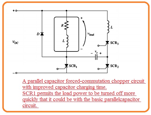
- The circuitry having decreased capacitor charging time is can see here.
- In this circuitry SCR1 triggered at the similar time, SCR1 is and the capacitor can charge very rapidly.
- It permits the current to gets off with speed if it is required to operate.
- In this circuitry of this type, the freewheeling diode is very significant.
- When SCR1 forcibly stops the current from the inductive load should has a different way exist to it or can disturb the SCR.

