 Hello, friends welcome to the new post. In this post, we will have a detailed look at VOLTAGE VARIATION BY AC PHASE CONTROL. The voltage applied at the motor is the very basic application at the motor control. The SCR and Triac offer the easy method for regulation of the average value of voltage provided to output or load through varying the phase angle over which source voltage is connected.
In this post, we will cover the basics of voltage variation through ac phase control. So let’s get started with VOLTAGE VARIATION BY AC PHASE CONTROL.
AC Phase Control for a DC Load Driven from an AC Source
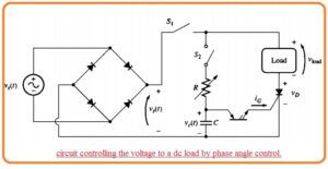
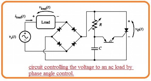
- The below figure explains the features of phase angle power control
- It indicates the voltage control circuitry having resistance dc load provided to an as the source.
- The SCR in the circuitry has breakdown voltage IG=0 A which is larger than the maximum voltage in the circuitry but PNPN diodes has less breakdown voltage generally close to ten volts.
- The full-wave bridge circuitry makes sure that voltage given at the SCR and load will be dc.
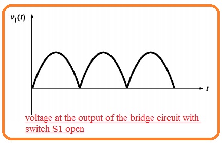
- If the switch S1 in above figure is not closed then the voltage VI at points of rectifier will be full-wave rectified type of input voltage.
- If switch S1 is closed and switch S2 is open then the SCR will be in off state.
- IT si good since the voltage out of the rectifier will not get larger the VBO for SCR. Because the SCR is open circuitry the current passing from it and load and voltage over the load will be 0.
- Let us assume that the switch S2 is closed Then at start of ist half cycle after the switch is not open voltage creation about the RC system and the capacitor starts to charge.
- Though time the capacitor is charging SCR is off state because the voltage applied to across it has not become larger than VBO.
- With the passage of time, the capacitor gets charged to the break-over voltage of the PNPN diode and the PNPN diode start operation.
- The current passing from the capacitor and PNPN diode move through the gate terminal of SCR decreasing the VBO about SCR and on it.
- If the SCR is on the current passing from it and load. The current passing lasts for the other portion of the half-cycle though the capacitor becomes discharged. Because the SCR gets off only when its current decreases less the IH.
- At the start, the next half-cycle the SCR is in off state. The RC circuitry gets charge again to a limited time interval and triggers the PNPN diode.
- The PNPN diode transmits the current to the gate of SCR it becomes on.
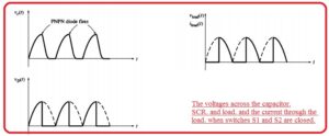
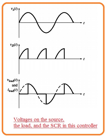
- When the SCR is on for the other portion of the cycle. The voltage and current signal for the circuitry can be seen here.
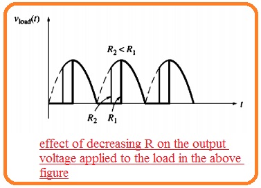
- Here is a question arises how the power provided to load varied? Assume that value of R is reduced.
- Then at the start of every half cycle, the capacitor will gets charged very fastly and SCR will burn soon.
- As the SCR will not retain further retain in half cycle some part of more power will be given to the load.
- The resistance R in the circuitry regulates the power movement to the load in the circuitry.
- The power offered to the load is a function of the time which the SCR gets burn so further power will be needed.
- The firing time of the SCR has explained in the firing angle here the firing angle is the angle of the applied sine signal at the time of firing.
AC Phase Angle Control for an AC Load
- This is the simple method to do modification of circuitry in the below figure.
- FOr control the ac load just through the load from the dc portion of circuitry to the location after rectifiers.
- The resultant circuitry can see here.
- Its voltage and circuitry signal can see here.
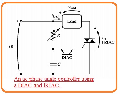
- Though there is an easy method to creates an ac power controller if the simple circuitry is employed then diode bridge circuitry can be totally removed from the circuitry.
- Since both DIAC and TRIAC are 2-way components they are working equally at any half cycle of ac source.
- The ac phase power controller has diac and triac can see here.
Effect of Inductive Loads on Phase Angle Control
- If the load connected to the phase angle controller is inductance like motors there will be some problems are occurring at the function of the controller.
- Through the type of inductance, the current in inductive load not changes an instant basis.
- It indicates that current at the load will not increase instantly at the firing of the half-cycle. At endpoint of half-cycle, the inductive voltage at the load will retain the component in half cycle till the current passing from the load and SCR decreases to IH
- The diagram shown below disturbs the factor of this delay processing voltage and current signals at the circuitry shown above figure.
- The high inductance in the load can produce 2 potentially some issues having a phase controller.
- The inductance can affect the current creating to very sow in case SCR is turned on which it does not larger the IH before teh gate current diminishes.
- If it occurs the SCR will not operate in on state since the current is less than holding current.
- If the current lasts for time to disturning the holding current after the ending of the cycle the voltage given can create larger in the subsequent cycle to retain the current passing and SCR will never get off.
- The basic outcome of this ist issues is the usage of certain circuitry to offers the larger gate current pulse at the SCR.
- This high pulse permits lots of time for the current passing from teh SCR to gets become the Ih. Allowing the component to retain on for the other part of half cycle.
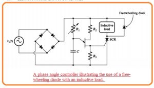
- The solution for the 2nd issue is to use a freewheeling diode. The freewheeling diode is a diode put about the load and directed in such way that it does not operate for normal movement of current.
- This diode can be seen here.
- At the endpoint of the half-cycle, the current is inductive load will try to retain the passing in the similar direction as it operating.
- The voltage will create at the load having polarity needed to retain the current passing.
- This voltage will be forward biased the freewheeling diode and it provides a way for the discharging current through the load.
- In this way, the SCR will get on lifting the needs for the current of the conductor to lose to 0


