 Hello, readers welcome to the new post. In this post, we will have a detailed look at Introduction to DIAC. It is two dimensions or full-wave operating device that can operate in two directions or polarities in reverse and forward biasing. Its name DIAC is a combination of two words diode and AC switch.Its common applications are the switching of Triac also employed in lights dimmers.
It also parts of the circuit used to start the fluorescent lamps. In this post we will cover its working operation applications and some other related parameters. So let’s get started with Introduction to DIAC,
Introduction to DIAC
- The full form of DIAC is a diode for alternating current. Its name is the can operate in both directions forward and reverse.
- It belongs to the thyristor groups and generally employed in triggering of triac and another category of thyristors.
- Its operation is such that when applied voltage is larger than the break over voltage that its conducts.
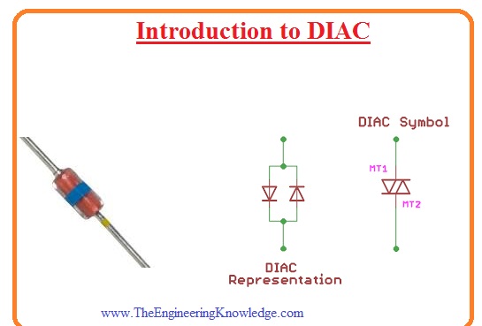
- The general packaging in which it exists is leaded packaging surface mounted packaging.
- In some applications, its employed with the triac so gets in single ICs.
- It sometimes is known as symmetrical diodes it is due to the symmetry of the characteristic curve.
DIAC Construction
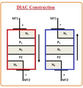
- The structure of DIAC is like the construction of transistor with some difference that there is no base terminal in diac and there is similar doping level for 3 layers and it offered similar switching features for forward and reverse bias
- In the below figure, we can see the normal structure of diac. The above-mentioned terminal of diac MT1 and MT2 can seen here and used for the movement of current in two directions.
- This module is created in a structure having 5 layers and these layers close to points have a combination of positive and negative sheets.
Symbol of DIAC
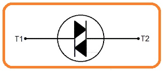
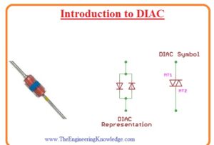
- The symbolic representation of diac combination of 2 diodes linked in parallel combination having reveres structure and has 2 points.
- As the diac is two-dimensional so its terminal can not be named as anode and cathode. Its terminal is known as A1 and A2 or MT1 and MT2 here MT full form is the main terminals.
DIAC Working Operation
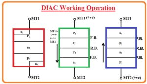
- The below figure indicates the working of DIAC according to their polarities. Suppose that MT1 points is at positive polarity in results P1 layers close to the MT1 get energized.
- The flow of current will take place in the order of P1, N2 P2 and N3.
- If the current is passing from MT1 to MT2 terminals then junction among the P1 and N2 and P2 and N3 will in forward biased state and pn junction for N2 and P2 will be reversed biased.
- In case if MT2 is positive polarity then layers close to MT2 will be activated and current flows in a sequence of P2 N2 P1 and N1. From this we can observe that the bidirectional behavior of DIAC is fulfill.
DIAC VI Characteristic
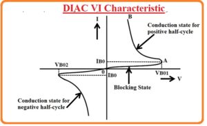
- The VI curve odd DIAC is like the letter Z and it exists in the ist and 3rd quadrants due to operation for positive and negative polarity.
- The part of the curve that exists in the first quadrant shows the positive cycle where the current flowing from MT1 to MT2 and the third quadrant indicates that current passing from MT2 to Mt1
- At the start resistance of DIAC is large since of the reverse bias junction among the layers so here is a small amount of leakage current passing from DIAC it is denoted as blocking state in the figure.
- When the voltage is given is close to the breakdown voltage resistance of diac loss suddenly and its operation started that causes the decrement in the voltage-current initiate rising, this step shown in the figure as conduction state.
- The value of breakdown voltage is thirty volts the value of breakdown voltage lies at the category of the component.
That is a detailed post about DIAC i tried to cover each and every parameters related to DIAC if you have to know further about DIAC ask in the comments. Thanks for sharing have a nice day.


