Hello, friends, welcome to the learning platform. In this post, we will have a detailed look at Introduction to Transformer. There are numerous devices used in our electrical power system, such as a motor generator, that are further divided into the ac motor, dc motor, and similar ac generator, ac motor. The work of a motor transforms the electrical power into mechanical power, and a generator transforms mechanical power into electrical power.
There is such a device used in the power system that not only generates and transforms power but also varies the voltage level from one to another, called a transformer. In other words, the value of the voltage at its input will be different from the value of the voltage at its output. In this post, we will define its working, application construction, and some other parts with the details. So let’s get started with Introduction to Transformers.
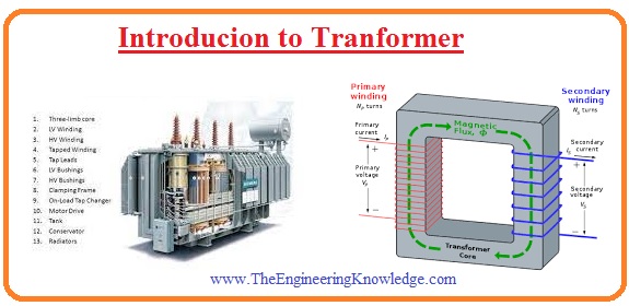
Introduction to Transformer
- The transformer is an electrical instrument that used to vary the voltage level from one to another with the use of a magnetic field.
- If the voltage level is decreasing at the output, it is called a step-down and if it increases, it is called a step-up transformer.
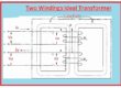
- There are 2 or more than 2 windings wounded at a single core of ferromagnetic material.
- There is no physical link between these two windings, but they are linked magnetically.
- One winding of a transformer is linked to the input supply, and the other is linked to the output or load.
- The windings of the transformer that are attached to the input are called primary, and others are called secondary.
- If in certain cases there are 3rd windings used, that is known as tertiary windings.
- The working phenomena of transformers depend on the Faraday Law, which says the rate of change of flux induces the voltage in the conductor where the flux is varying.
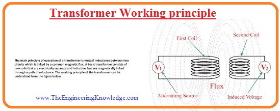
Transformer Working principle
- The working principle of transformer is followed the mutual induction that says change of flux link to other windings or conductor material induces voltages.
- As there is 2 windings in the transformer when ac supply is given to the input or primary windings then due to supply flux is produced in the windings.
- The flux induced in the primary windings also linked to the second windings through passing the core of the transformer and voltage induces in the secondary windings.
- The value of voltage induced at secondary windings is dependent on the number of turns at secondary windings.
- There is some part of flux which not crosses the secondary winding is known as leakage flux
- The induced voltage is also followed the Faraday law. The quantity of voltage induced relies on the number of turns windings at respective sides.
V1/V2 = N1/N2
Construction of transformer
- The main parts of the transformer are discussed below.
Transformer Core
- The core is constructed with the substance having a high value of permeability, which means this material offers a path that has less value of reluctance to flow of flux from primary to secondary.
- The core is normally designed in the form of a square or rectangular according to requirements.
- If the transformer core is created with a ferromagnetic material like iron, then a large amount of flux flows from one winding to the other due to less flux leakage.
- The core is created through silicon and has lamination. The lamination helps to reduce the eddy current.
- The thickness of lamination is about 0.35 to five millimeters.
Tranfsforemr Conservator
- In this part of the transformer, there is the conservation of oil. It is a cylinder-like configuration that has and is placed at the upper portion of the transformer.
- The oil level in this part is mid, so when it expands due to temperature, it rises to the upper level.
Transformer Winding
- Normally 2 windings exist in the transformer; the first is primary, where input is linked, and the second is secondary, where output is taken.
- The windings of the transformer are created through the use of high-level copper.
- There is insulation rapped at the conductors through which the current is passing.
- The voltage given to the primary windings is known as primary voltage, and in a result, the voltage produced at secondary windings is secondary voltage.
- So voltage is named LV and HV according to a voltage level.
Transformer type
Step-up transformer
- In this category of transformer, there is less number of turns at a primary and a large number of turns at a secondary.
- This configuration of the transformer helps to increase the voltage level at the secondary side more than the primary side.
Step-down transformer
- In this type of transformer, there is a large number of turns at primary and a smaller number of turns at secondary.
- The voltage value of secondary is less than primary, so it prefers such applications where less voltage is needed.
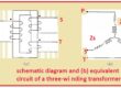
Core Type Transformation
- In this category of transformer windings, it is wound in such a configuration that it covers the core, or, as you can say, the core is the outer side.
- Normally, this type of arrangement uses a distribution transformer.
- The cylinder-shaped windings are configured in this type of transformer, and the windings shape can be rectangle or circular.
- The small-size transformer uses a rectangle-shaped core.
Shell Type of Transformer
- In this type of transformer, the core is on the outer side and the winding is wound on the inner side.
- In this transformer, two windings are positioned at one arm of the core. The configuration of windings is like the multiple-layer disc.
- To make separation and avoid layers from practical connection, insulation is wrapped.
That is a detailed post about Transformer if you have any further queries mentioned in the comments. See you in the next post have a nice day.