
Hi fellows. I hope all of you are fine. As you already know, we have started a series of PLC articles. In the last lecture, we discussed a detailed introduction to PLC. In today’s tutorial, I am going to explain to you the detailed article on parts of PLC. PLCs have become very important for our industrial life; they have made many processes very easy to control and monitor. It eliminates the tough circuitry of relays, which were very complex to handle and implement.
As we discussed in our last tutorial about it, it is a very flexible, reliable, and fast time-response controller. Its troubleshooting is very easy, meaning we can solve problems existing in circuits by seeing them on the monitor. But in case of a relay, it’s not easy to find the fault and solve it. So let’s get started with the parts of the plc.
Parts of a PLC (Programmable Logic Controller)
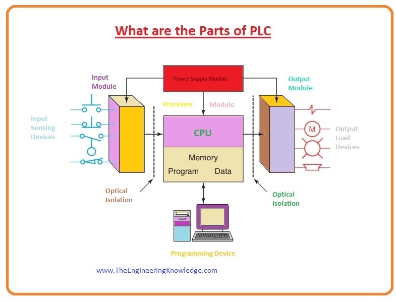
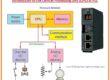
There are two main parts of a PLC. Which has further divided into many parts, like CPU, input and output sections, input supply, and different programming modules.
The PLC structural design can consist of hardware and software or both.
There are also two restrictions when choosing a PLC: the first one is open architecture and the second is closed architecture.
Guys, I hope you all are aware of the iPhone structure, which is also a closed architecture, meaning we cannot connect other company chargers or a data cable with it.
Like iPhone PLC, the closed structure is also not supported by other companies’ instruments, so be careful about this structure.
In the case of open architecture, you can easily connect your devices with other manufacturing company modules.
Moreover, though the main ideas are similar in all means of software design, there can be small changes in speaking, memory distribution, recovery, and data management for altered modules.
Subsequently, PLC programs cannot be swapped amid dissimilar PLC builders.
There are two methods by which inputs and outputs of a PLC are connected with it: the first is the fixed type and the second is the modular type.
PLC Fixed Input/Output Configuration
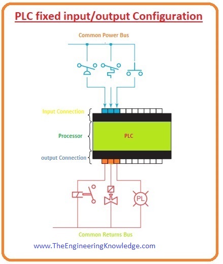
Fixed input and output configurations are shown in a given diagram. It is a small PLC that exists in a single package, and there are no separate removable parts.
In his type of casing, the process and inputs/outputs are connected with each other, and in this casing, there are fixed terminals for inputs and outputs to make connections.
The chief benefit of this category of packing is a lesser price. The quantity of existing input and output points differs and typically can be extended by purchasing extra components of fixed inputs and outputs.
One drawback of this packaging is its absence of flexibility; we are restricted to following the instructions that are written on the casing.
One thing in this configuration that is noticeable is that if one part of it is damaged, then we have to replace the complete unit.
PLC Modular Input and Output Configuration
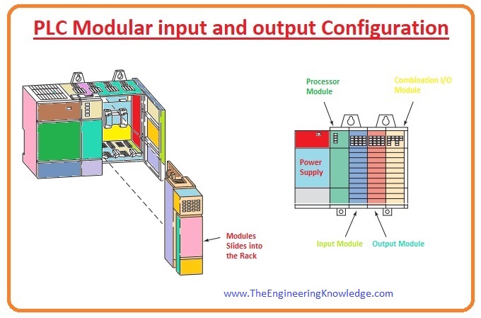
- Plc modular input and output configuration is divided into different parts in which we can connect different separate devices.
- These properties insist us to choose this flexible unit.
- We can select units accessible from the producer and connect them any way according to our wish.
- The elementary modular controller comprises a shelf, input supply, CPU, input and output, and an operative line for software design and observing.
- The components connect with a stand or rack. When a unit is put into the frame, it makes links electrically with the sequence of the connection named as backplane that is manufactured at the backside of the rack.
- The PLC CPU is also linked to the backplane and can send and receive data to all the components in the stand.
Power Supply of PLC
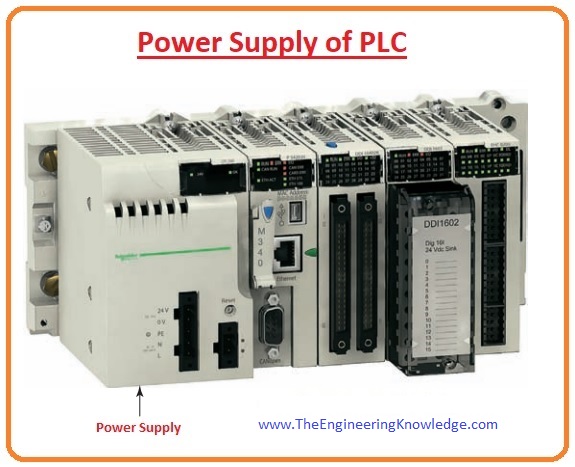
- The rack provides the dc power to components that are connected to it.
- For big PLC schemes, this supply is not enough for components to connect with it, for larger schemes, supply is given by separate DC or AC systems.
- For small PLC networks, the power supply can be used to power field instruments.
Processor of PLC
- The processor of a PLC works like the brain of a human, which means it controls every process of plc.
- The processor of the PLC comprises a microprocessor for the implementation of logic and monitoring the signal communication process between different parts.
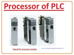
- The processor needs memory or storage space for storing the outcomes of the logical processes done by the microprocessor.
- Memory is also compulsory for the program: EPROM (erasable programmable read-only memory) or EEPROM (electrically erasable programmable read-only memory), plus RAM (random access memory).
- The Central Processing Unit regulates all PLC action and is intended so that the operator can put the anticipated program in ladder logic.
- The PLC program is implemented as a portion of a repetitive procedure denoted as a scan; it is explained in a given diagram.
- A distinctive PLC scan reads the input status with the Central Processing Unit. Then, the submission program is implemented.
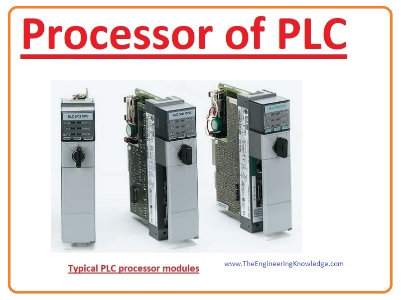
- When the program implementation is finished, the Central Processing Unit does interior analytical and messaging tasks. Subsequently, the grade of all outputs is simplified.
- This procedure is repeated continuously for the time the PLC is working.
Input and output connections of PLC
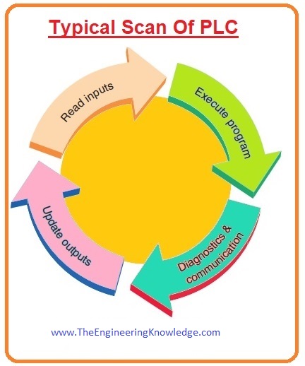
The input and output connections make the network by which other working instruments are linked with the plc controller.
The motive of this interfacing is to convert the numerous signals obtained from or referred to outside instruments.
Input components like push-pull buttons, limiting switches, and sensing instruments are connected to the input points.
Output instruments like less current-consuming motors, starters, solenoid regulators, and pointer bulbs are connected to the output connections.
To electrically separate the interior constituents from the input and output terminals, PLCs usually use a visual isolator, which uses light to join the circuits with each other.
The exterior instruments are also known as field input and output devices.
Ladder Logic Language and Programmable Device of PLC
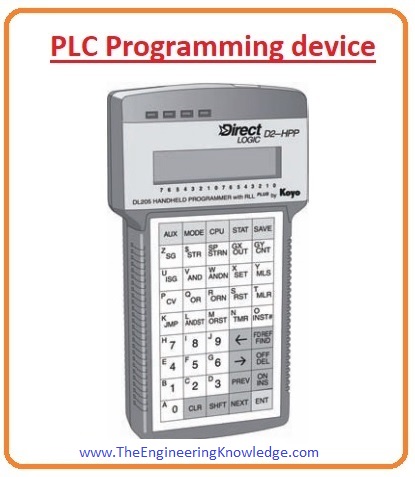
- Programming instruments are used to implement the specific program into the storage of the CPU.
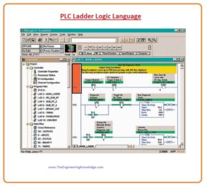
- We can implement our program by a ladder logic language; it is a very famous and easy-to-understand language.
In place of letters, ladder logic language uses graphical signs that display their proposed consequence.
A program in ladder language is like a diagram for relay controller circuitry. It is a distinct language inscribed to make it simpler for a person who is used to relay logic controllers to program the programmable logic controller.
Portable programming devices are occasionally used to implement a program to small PLC controllers since they are less costly and easy to use.
When they are connected to the PLC, they work to implement and regulate the program.
Mobile tablets and laptops are often used on the workshop floor for troubleshooting apparatus, adjusting programs, and transporting programs to numerous pieces of machinery.
A PC is the normally used programming instrument. Most PLCs have software available so that a personal computer is used as the programming instrument.
This software permits operators to make, correct, text, save, and troubleshoot ladder logic programs.
The monitor shows more programs than portable devices like mobiles, so it makes a program easily understandable.
The monitor shows more programs than portable devices like mobiles, so it makes a program easily understandable.
- The PC interconnects with the PLC CPU by a sequential or parallel statistics transportation connection or Ethernet.
- If the programming component is not in use, it can be freed and detached. Eliminating the programming component will not disturb the process of the operator program.
- A program is an operator-established sequence of commands which guides the PLC to implement different activities.
- A programming language delivers guidelines for merging the commands so that they give the desired output.
- The Relay ladder logic is the customary programming language which used for PLCs. Its foundation is built on the electromechanical relay controller.
- The (RLL) program sketchily represents steps of connections, loops, and distinctive teaching chunks.
- Relay ladder logic was initially designed for informal usage and sympathetic for its operators and has been altered to retain with the growing needs of industry’s controller essentials.

So it is a complete and detailed article on the parts of PLC, each and every part of PLC has mentioned in this tutorial. See you in the next tutorial working principle of PLC.




If you desire to improve your knowledge simply keep visiting this web page and be updated with the latest information posted here.
Very educative post, learned a lot. So glad I discovered your
blog, and managed to learn new things. Keep posting articles
that are informative, it is really valuable.
King regards,
Thompson Zacho