
Hello, fellows, I hope all of you are having fun in your life. In today’s tutorial, we will have a look at the methods of improving commutation. In a DC machine the commutation is a very important process through which alternating current production in machines is converted into DC at the output terminals. For this process, commutator segments are placed at the rotor of DC machines that convert AC into DC. During this commutation, some problems occur that we discussed in detail in the previous tutorial on commutation problems: the first one is armature reaction, and the second one is L di/dt voltages.
These two issues severely affect the commutation process. In this tutorial, we will discuss the solution to these issues that occur with commutation. So let’s get started with the solutions to the problems with commutation.
Methods of Improving Commutation
To solve the problems of commutation armature reaction and L di/dt, there are three main techniques that are listed here.
Brush shifting.
Commutating poles or interpoles.
Compensating windings.
Let’s discuss these 3 techniques in detail.
Brush Shifting
The first time an effort was done to make some improvement in the commutation process was to decrease the flashing that occurs at the brush due to neutral plane shift and L di/dt voltages.
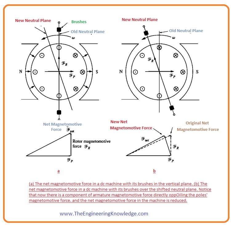
To solve these issues that times engineers thought that with the variation in the position of the neutral plane (the neutral plane is the position where the rotor of the machine is rotating parallel to the magnetic flux lines; that is why an axis lying in this plane is known as the magnetic neutral axis (MNA)), the shift there should also change the position of the carbon brushes.
It looks like a good option, but it also creates some problems. The neutral plane changes its position with load variation. If our machine is a DC motor, due to some certain load variations, it behaves like a generator.
Then we have to lower a man on the machine to adjust the position of the position of brushes as the neutral plane changes according to load variation.
Let’s suppose that if we vary the position of the brushes according to the neutral plan shift, it might decrease the flashing at the brushes; nevertheless, it increases the flux-weakening effect of the armature reaction in the machine.
It is correct due to these two factors.
The vector element of mmf at the rotor opposes the mmf of the poles of the machine. You can see this in a given figure.
The variation in armature current spreading origins the flux to bunch up, making the saturation portion of the poles larger.
An additional somewhat different method occasionally taken was to fix the brushes at a compromising location (it means no flashing occurs at 2/3 of full load).
In this situation, the motor flashed at zero load condition and slightly at full load, but if it consumed the furthest of its life functioning at around 2/3 of full load, then flashing was lessened.
Such a machine cannot operate as a generator; the flashing can cause a serious disaster.
After 1910, the brush-shifting technique for the reduction of flashing has been eliminated.
Nowadays, this method is only used for DC motors of small rating, not for generators. For these motors, this technique is less expensive than others
Commutating Poles or Interpoles
- As we discussed above, a permanent magnet needs to change the position of the carbon brushes with the load variation; there is another solution to this issue: we eliminate the voltage in the conductor that is doing commutation. In this way, flashing will be decreased.
- To do this, small poles that are known as interpoles or commutating poles are introduced among the main poles of the machine.
- These small poles are connected with the wire that is used in the commutation process. These small poles have their own flux; this flux will interact with the conductor flux in such a way that it will minimize the effect of the flux of the conductor.
- In this way, flashing can be decreased at commutator segments. One question will come to your mind: do these small poles also affect the operation of a machine?
- Certainly, not these poles and their flux do affect the operation of the machine; they are smaller in size, and their flux strength is so low that it only affects some conductors that are doing commutation.
- You can note that these small poles are not affecting the flux weakening effect caused by the armature reaction; simply, we can see that these small poles only reduce the flashing occurring on the commutators, not the armature reactions.
How is annulment of the voltage in the commutator segments generated for all values of loads?
For this there is another winding called the interpole winding, which is connected with the armature winding of the machine. It is shown in this given figure.
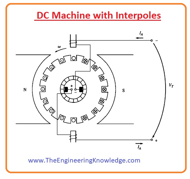
With the increment in load attached to the machine, the armature current also increases; with that, shifting of a neutral plane and L di/dt voltage also increase.
These 2 factors also increase the voltages of conductive wires that are taking part in the commutation process.
The flux of interpoles also increases, which decreases the effect of the voltage caused by the shifting of a neutral plane.
The final outcome is that their effects cancel over a wide range of loads. You can see that interpoles or commutation poles operate for both motor and generator operation, as when the machine alters from motor to generator, the direction of current in its armature winding and interpoles also changes.
What is the polarity of interpoles’ flux?
As the interpoles are linked with the conductor that is used in the commutation process, its voltage direction is reversed to the voltages caused by the neutral plane shifting and L di/dt.
If our machine is a generator, as we have known that in a generator the shifting of the direction of the neutral plane is in the direction in which the rotor is rotating. You can see it in the given figure.

It means that the wire that is used in the commutation process has a similar voltage polarity to the pole they left behind.
To decrease the effect of these voltages, the polarity of the interpoles’ flux should be opposite.
In the case of a motor, the shifting of the neutral plane is opposite to the direction of rotation of the rotor and the
In a motor, however, the neutral plane shifts opposite to the direction of rotation, and the flux of conductors taking part in the commutation has similar polarity to the pole towards which it is moving.
To decrease the effect of this flux, the polarity of the interpoles’ flux is similar to the polarity of the previous main pole.
So we can say that,
The polarity of interpoles in the case of a generator is similar to the next upcoming main pole.
WHILE in the case of a motor, the polarity of the interpoles should be equal to the polarity of the previous main pole.
The practical implementation of interpoles nowadays is very common because it is the less expensive solution for reducing the flashing at the commutators.
You can see these poles in almost every DC machine of one horsepower or larger.
One important thing you must know is that this pole has no effect on flux scattering under the pole faces, therefor weakening of flux still exists.
Mostly intermediate size, motors use interpoles for flashing or sparking problems with them, leaving the weakening of flux in the machine.
Compensating Windings
For severe duty cycle motors, the flux weakening effect that is caused by the armature reaction can create a serious problem.
To entirely eliminate the armature reaction and also eliminate flux weakening and neutral plane shifting, numerous methods have been introduced. Like interpoles and brush shifting that we have discussed.
- There is another method to solve these issues in DC machines: place another winding on the poles parallel to the rotor called a compensating winding. These windings minimize the effect of the armature winding.
- This compensating winding is attached with the armature winding in series, so that variations in load armature current also vary the value of current in the compensating winding.
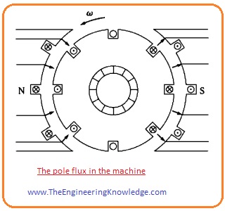
- In the figure given below, you can see the flux of the poles.
- In this below figure, you can see the flux of the armature winding at the rotor and the flux of the compensating winding.
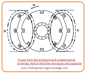
- In the figure below, you can see that the addition of pole flux, armature winding flux, and compensating winding flux that is equivalent to the flux of pole.
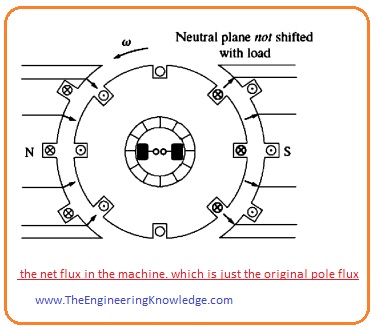
- The figure given below explains the detailed effect of the compensating winding in dc machines.
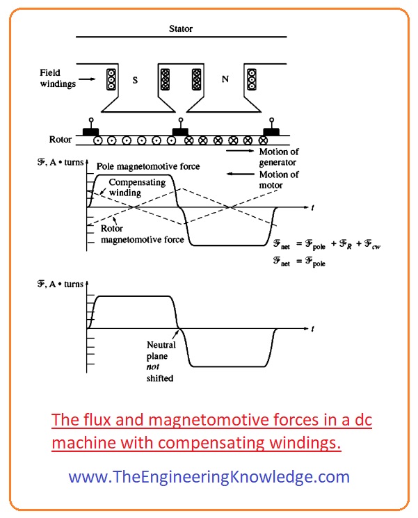
- You can see that the mmf caused by the compensating winding is equivalent and opposite to the mmf of the rotor at each point under the effect of the poles.
- The resultant net mmf is the mmf due to the poles, so the flux in the machine is unaffected irrespective of variation in load attached with the machine.
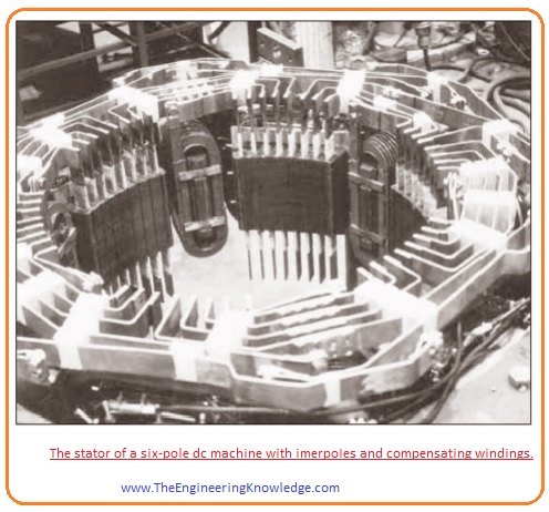
- In this given figure, you can see that the stator of a larger rating dc machine with compensating windings is shown.
Disadvantage of Compansating winding
- The main drawback of compensating is that its cost is very high, as its locations are always in front of the poles of the machine.
- The DC motor should have interpoles, as compensating windings do not minimize the L di/dt effects.
- The strength of interpoles should not be as high, however, as they are minimizing only L di/dt voltages and not the voltages caused by the shifting of the plane.
- The use of both the interpoles and compensating winding in a machine makes it too expensive, so these windings are used only where the tremendously severe nature of a motor’s duty asks for them.
Read also
- Commutation Problems in DC Machines
- Commutation and Armature Construction DC Machines
- Commutation in Four Loop DC Machine
So friends, that is the detailed tutorial on the Methods of Improving Commutation I have mentioned every parameter related to the Method of Improving Commutation. If you have any questions about this post ask in the comments. See you in the next tutorial.




In your article title “Methods of Improving Commutation”, section “What is the polarity of Interpol’s flux?”, there’s one incomplete sentence:
In case of motor, the shifting of neutral plane is opposite to the direction of rotation of rotor and the…
Please provide the missing words.
Many thanks for your excellent article!
Best regards,
Hoai
thanks dear
I have completed missing words