 Hello friends, I hope you all are doing great. In today’s tutorial, we will have a look at Introduction to Differential Amplifier. It is a type of amplifier which amplify the difference of two input signal. There are 2 modes of operation for this amplifier first is a common mode in which both inputs are the same and the second one is a differential mode in which two inputs are different.
This amplifier configuration is normally used in analog ICs circuits arrangements. In today’s post, we will have a detailed look at its working, circuit, and related parameters. So let’s get started with Introduction to Differential Amplifier.
Introduction to Differential Amplifier
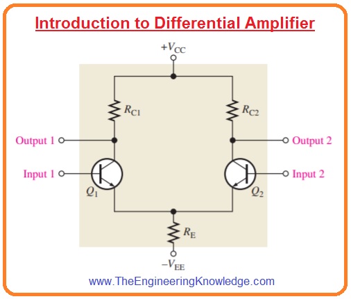
- In below figure, the basic differential amplifier circuit is shown.
- You can see that this circuitry has 2 inputs and 2 outputs.
- The below figure defines the dc bias analysis of differential amplifier.
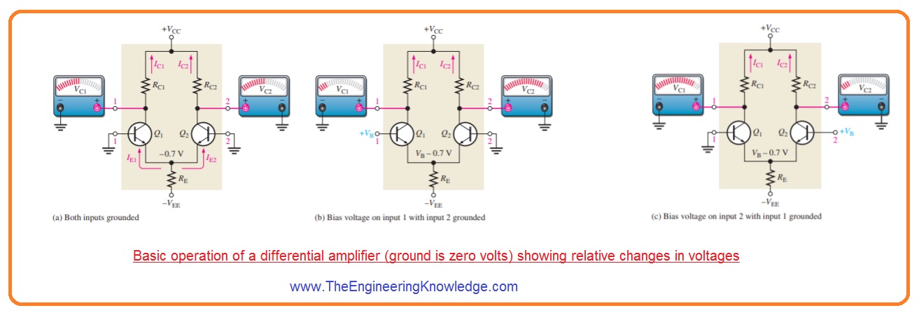
- First of all the voltage across both inputs is zero volts and both emitters have a voltage -0.7 volts as shown in figure denoted as (a).
- It is supposed that transistors are definitely matched with each other during construction so their dc emitter currents are at the same level when there is no voltage at inputs.
IE1=IE2
- As both emitters current linked through the reistance RE.
IE1=IE2=IRE/2
- Here
IRE=(VE-VEE)/RE
- According to estimation, we have IC=IE
IC1=IC2=IRE/2
- As both collector currents and collector resistances are the same for zero input voltage.
VC1=VC2=VCC-IC1RC1
- This condition is defined in figure denoted as (a).
- In figure denoted as (b) input 2 is connected with the ground and positive biased voltage is provided at input one.
- The positive voltage at the base of transistor Q1 increases the IC1 which decreases the VC1 and decrement in IC2 cause an increment in VC2.
- In figure denoted as (c) input, one is at connected with the ground, and second input is connected with the positive bias voltage.
- Positive bias voltage causes the transistor Q2 to operate more that increases current IC2.
- Also, the value of the emitter voltage is increased.
- It decreases the forward biasing of transistor Q1 as its base is connected with the ground which causes current IC1 to decrease.
- The consequence is that the increment in current IC2 generates a decrement in VC2 and the decrement in current IC1 cause voltage VC1 to increase.
Modes of signal operation
Single-ended differential point
- When differential amplifier has such a configuration in which one input is at ground level and at other input voltages is provided. It is shown in figure.
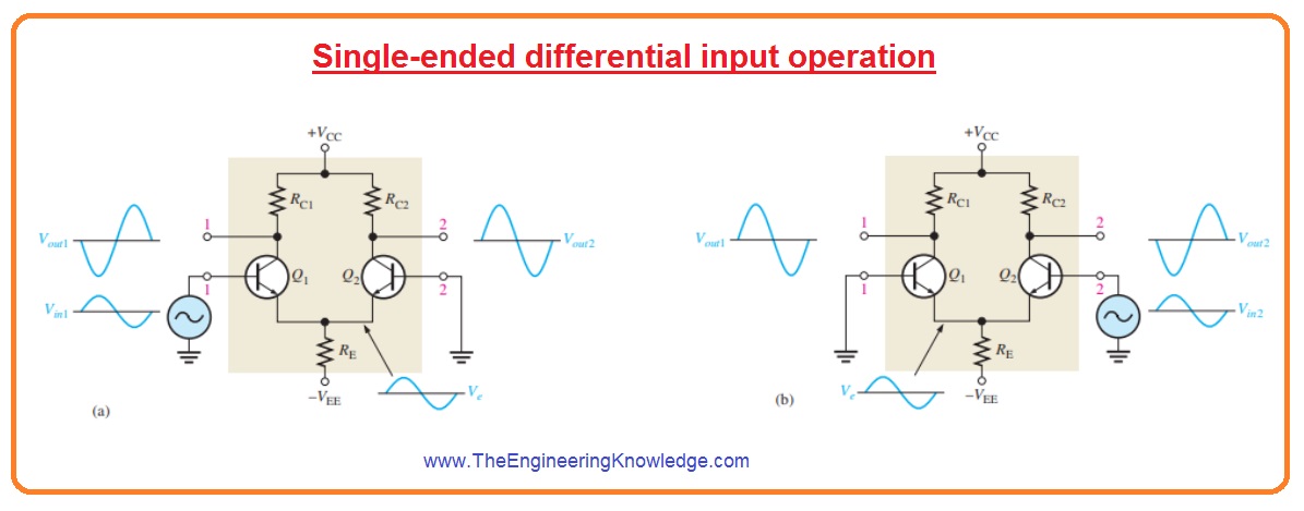
- The condition when voltage is provided to first input as denoted in figure (a) inverted amplified signal voltage is shown at output one.
- With that signal voltage exits in phase at the emitter of transistor Q1.
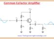
- As the emitters of transistors Q1 and Q2 are common the signal of the emitter will be input to the transistor Q2 that operates as a common emitter amplifier.
- In the figure denoted as (b) signal is provided to the input two and the first input is connected with the ground.
- In a result, an amplified inverted signal appears at the output two.
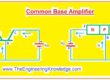
- In this condition transistor, Q1 operates as a common base amplifier and a non-inverted signal is shown at output one.
Double-ended differential inputs
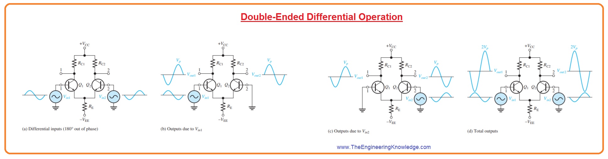
- In this input arrangement, 2 signals of opposite polarity are given to the input it shown in below figure denoted as (a).
- Every input affects the output.
- Figure denoted as (b) shows the output voltage at due to signal at input one working as a single-ended input.
- Figure denoted as c shows the output voltage due to the voltage at the second input working as a single-ended input.
- You can note that in circuits denoted as (b) and (c) polarity of a signal at input one is the same.
- It also for output two both are the same polarity.
- By superimposing both outputs one voltage signals and both output 2 signals you will get total output signal as shown in figure denoted as d.
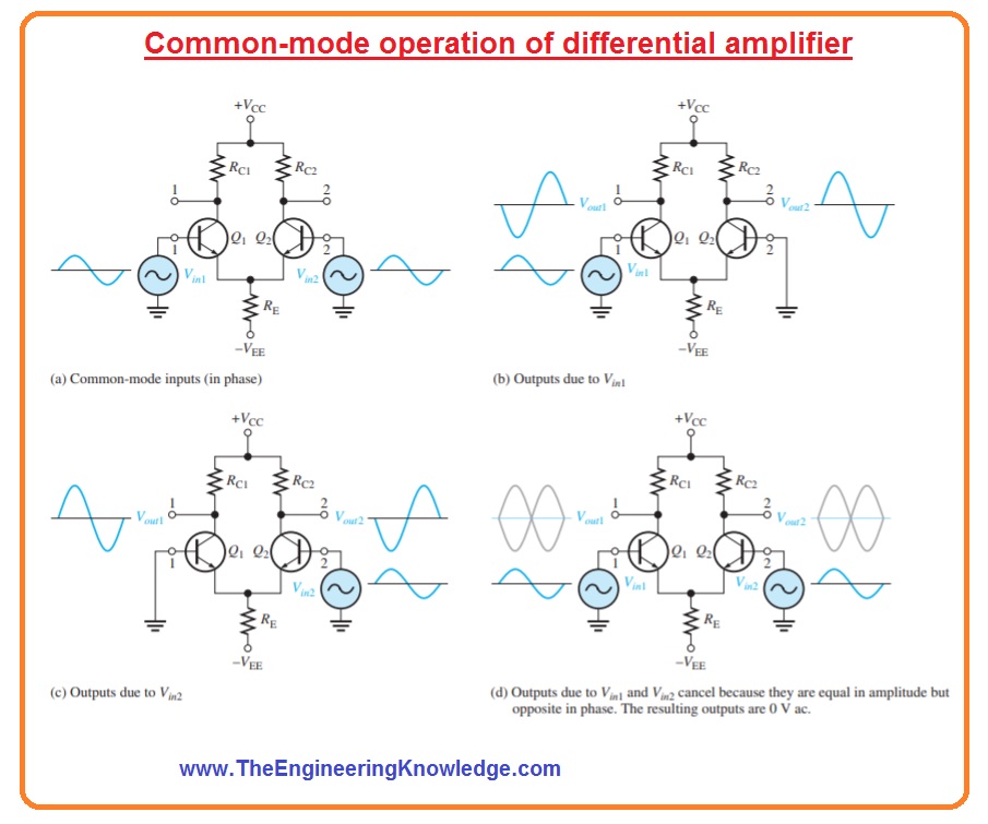
Common mode input
- The most important factor of operation of differential amplifier can be seen to take into consideration common-mode condition.
- In this condition, two signal voltages of similar frequency, phase and amplitude are provided to the 2 inputs of an amplifier as shown in the figure denoted as (a).
- By taking a single input at one time we can understand the operation.
- Figure denoted as (b) shows the output due to the signal only on the first input.
- Figure denoted as (c) shows the output voltage signal due to the signal voltage at input two.
- Note that resultant signals at on output one have opposite polarity and are on output two.
- If the input signal is given at both of the signals the output will be superimposed and the resultant will be zero output voltage shown in the figure denoted as d.
- This process is known as common-mode rejection.
- This mode is important for such conditions when an unwanted signal comes at both inputs of differential amplifiers.
- Common mode rejection mode means that the undesired signal will not be shown at the output and not disturb the original signal.
- Common mode signal or noise is the consequence of the radiated energy on the input lines from neighbouring lines such as sixty hertz or other sources.
Common mode Rejection Ratio
- The required signal is obtained at single input or one or both inputs having opposite polarity.
- These required signals are get amplified and shown on the output as we have discussed above.
- An undesired signal existing at both input lines with the same polarity will cancel through the differential amplifier and not be shown at the outputs.
- The measurement of amplifiers’ ability to reject a common mode signal is a factor known as the common mode rejection ratio or CMRR.
- In ideal conditions differential amplifier gives a large value of gain for the required signal and 0 gain for the common mode signal.
- But a practical differential amplifier gives a very less value of common mode gain normally less than one while showing large differential voltage gain normally several thousand.
- The greater the differential gain of amplifiers concerning common mode gain the performance of the amplifier in terms of rejection common mode signal.
What is the main advantage of a differential amplifier?
- The main feature of the differential amplifier is that the signal common for both inputs is canceled and not shown in output voltage. Not required signals like noise, DC level, etc are removed when they get equally at both inputs.
What is the formula of differential amplifier?
- For certain circuits of differential amplifiers the input Vin is different between two input terminals that is equal to (V1-V2) and Gain = VOUT/(V1-V2).
Read also:
So, friends, it is a detailed post about differential amplifier if you have any question ask in comments. Thanks for reading.

Please contact me on Whatsapp: 44 7379 059887
I would love to talk with you guys 🙂
you can send me your queries I will guide you