 Hello friends, I hope you all are doing great. In today’s tutorial, we will have a look at How to Troubleshoot Amplifier Circuits. There are numerous types of amplifier circuits like common emitter amplifier, common base amplifier, common collector amplifier, differential amplifier. All these amplifiers we discussed in detail in a previous tutorial.
In today’s post, we will have a detailed look at amplifier troubleshooting for which we perform troubleshooting for a two-stage capacitively coupled amplifier. About the two-stage capacitively coupled amplifier we discussed with detail in a multistage amplifier. So let’s get started with How to Troubleshoot Amplifier Circuits.
How to Troubleshoot Amplifier Circuits
- When we have to troubleshoot any circuitry the main point that should be kept in mind is that there should be proper circuit labeled with the proper dc and voltage signal.
- You should know the value of accurate voltage for a circuit before measurement of any inaccurate value.
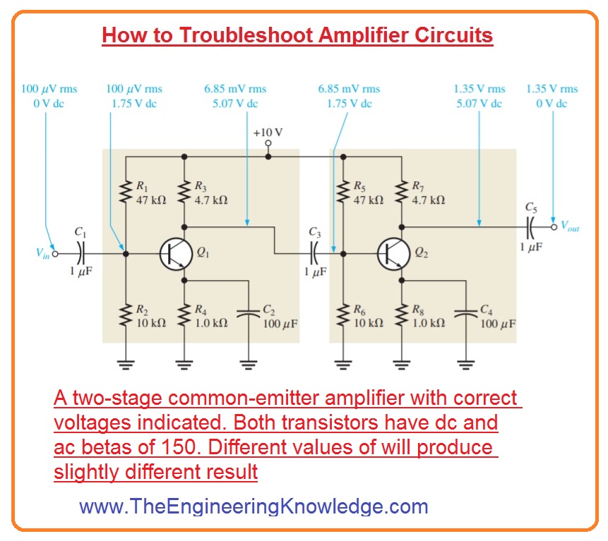
- In the below figure schematically for 2 stage amplifier circuits shown which we have discussed in multistage article with the detail.
Troubleshooting Procedure
The troubleshooting amplifier process is explained here
Analysis:
- In the analysis, we find that there is no output voltage exits.
- You also find that at the start circuit was working properly then became faulted.
- The visual analysis of the circuit was done and the probes related to broken connections, solder splashes, wire clipping or burns of different circuit components turned up nothing.
- From this, we concluded that the issue is an errored component in the circuitry or an open connection is exit.
- With that dc source voltage faulty or not exits.
Planning:
- We decided to use an oscilloscope for dc level checking or ac signal measurement at different points.
- With that, we decided to use the half-split method to find the voltage of the circuit and use in circuit transistor tester if the transistor is not working properly.
Measurement:
- To find the faulty component in the multistage amplifier there are five steps that are generally followed.
Step1: Perform power check
- find that the dc voltage is correct as shown in the figure.
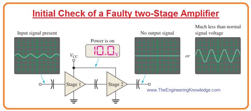
Step2: Find input/output voltage
- Suppose that the calculation shows that the input voltage is not faulty. There is not output signal or it is less than its required value as denoted in the above figure
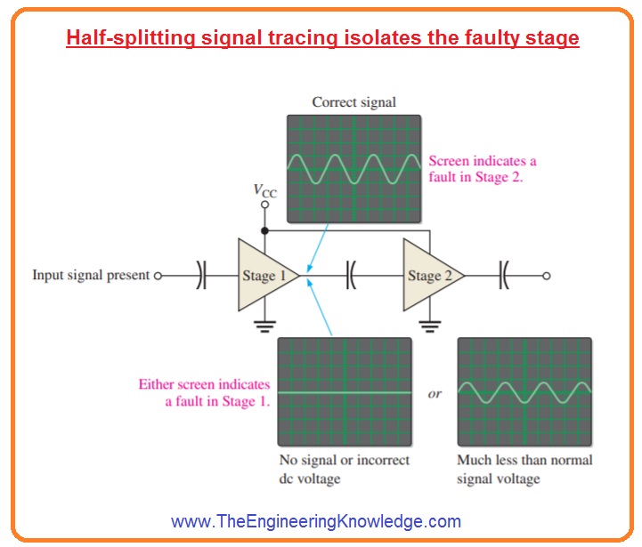
Step 3:use half splitting method of signal tracing
- Find the voltage at the output of the first amplifier or stage.
- The non-existence of voltage or voltage less than normal voltage value shows that the issue exists with the first stage.
- The errored DC voltage also denotes the problem with the first stage.
- If signal voltage and DC voltage are accurate at the output of the first stage then the issue is with 2nd
- This step is shown in the below figure.
Step4: use fault analysis
- Focus on the errored stage and find a failure of components that can generate faulty output.
- Likely faults:
- The failure of any resistance or transistor will generate a faulty dc bias voltage.
- The leaking bypass capacitor also disturbs the DC bias voltage.
- Further calculations are needed in this stage to separate the faulty component.
- Faulty ac voltage and likely errors are shown in the figure.

(a)Symptom 01
- The signal voltage at the output does not exist and dc voltage is correct.
Symptom 2:
- The signal voltage at the base is not exiting and the dc voltage is correct.
- Likely faults:
- The input coupling capacitor is open. It stops the signal from reaching to the base.
(b)Symptom:
- the accurate signal at the base but there is no output signal.
- Likely fault: The base of the transistor is an open circuit.
(c)Symptom:
- the signal voltage at the output is very low as compared to the normal value and dc voltage is good.
- Likely fault: bypass capacitor is open.
Step 5 : Repair
- After turning off the power repair the errored component. On the power and check proper function.
Read also:
- LM324 – Single Supply Quad Operational Amplifiers worksheet
- Difference Between An Operational Amplifier and Comparator
- Amplifier circuit using LA4440 IC
- Audio Amplifier Circuit
- Introduction to LM2902 Operational Amplifiers
- Difference Between Inverting and Non-Inverting Amplifier
FAQs
- There are many error that occurs with amplifiers common are no sound, distorted sound hum or buzz, , low output, and overheating.
- Each problem can be due to many reasons like loose connections, faulty components, or incorrect settings
- Connect the positive lead of the meter with the positive terminal on the amplifiers and connect the negative lead of the meter with the ground. if there is a reading close to 12 volts, then the amplifier is working accurately. if not then can be issue with amplifiers.
How do you troubleshoot an amp circuit?
- Check output, input, and power. Technicians can be surprised that complex issues can result in simple dirty power. So it takes some time to check and causes different issues.
- If there are domestic amplifiers, then note that it generates heat. Due to that overheating issues can causes. Normally these problems affect amplifiers when using devices for a longer time without break
- The main causes of noise can be stations on the signal path. From missing or error string grounding in electric guitar to defecting device cables to ageing electron tubes, etc
- The faulty tube will sound duller as compared to other tubes or sounds such as it comes with components rattling. That is a sign that tube is failed and needs replacement. Note that it is rare that more thatn one tube needed to replace.
So, friends, it is a detailed post about How to Troubleshoot Amplifier Circuits if you have any questions ask in the comments. Thanks for reading.