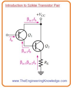
 Hello friends, I hope you all are doing great. In today’s tutorial, we will have a look at Introduction to Sziklai Transistor Pair. The Sziklai transistor pair first time was created by the George Sziklai to reduce problems related to decreased efficiency that occur for the Darlington pair. The other name of this configuration is compound Darlington pair or complementary feedback pair.
This pair of transistors comprises on 2 bipolar transistors one is NPN and second one is PNP. Its structural arrangements is like the Darlington pair. In today’s post, we will have a detailed look at its working, circuit, and some other related parameters. So let’s get started with Introduction to Sziklai Transistor Pair.
Introduction to Sziklai Transistor Pair
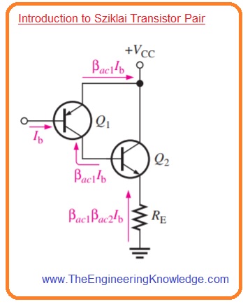
- In below figure Sziklai transistor pair is shown its construction is like the Darlington pair with the difference is that its configuration has 2 types of transistor contrary to Darlington pair which has the same type of transistor.
- The current gain of this transistor pair is like to the Darlington pair which we have discussed in the previous tutorial with the detailed.
- The main difference is that in sziklai pair Q2 base current is given by the collector of Q1 instead of the emitter current.
- The benefit of a Sziklai pair is that it uses less current to turn on than the Darlington pair as in this pair one potential barrier has to cross.
- Sometime Sziklai pair is used in conjunction with the Darlington pair as the output stage of power amplifier circuits.
- In this configuration transistors used in Sziklai are of similar type either NPN or PNP.
- It makes easy to get exactly matching of the output transistor, results in increment in high thermal stability and good sound quality in acoustic circuit applications.
Sziklai Transistor Pair Configuration
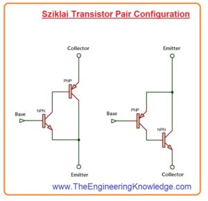
- There are 2 types of configuration for both Darlington and Sziklai pairs.
- But the base-emitter voltage drop of Sziklai is equal to the voltage drop of a normal transistor.
- Base emitter voltage loss of transistor is double.
- Sziklai pair is normally used in output stage of the push-pull amplifier circuit.
- In the above diagram, you can see 2 configurations for Sziklai pair. First is NPN and type Sziklai pair which has transistor Q1 as NPN and transistor Q2 is PNP.
- The second configuration is PNP type which has Q1 as PNP and Q2 as PNP.
- The value of gain for both transistor pairs is the same.
Sziklai Pair Gain: β=βQ1xβQ2+βQ1
Darlington Pair Gain:βQ1xβQ2+βQ1+βQ2
Sziklai Transistor Pair Working
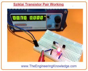
- We are going to discuss switching test of Sziklai pair with providing 0.7 volts.
- The required components are given here.
- 2N2222 which is NPN Transistor
- 2N2905 that is PNP Transistor
- Resistances of one hundred ohms, one thousand ohms, 10 thousand ohms
- Breadboard
- Wires for connection.
- After applying voltage sziklai pair start operates and led turn on.
- This indicates that to base-emitter voltage for pair is equal to the voltage of a single transistor.
- If we give pulse as input voltage at the base of NPN transistor denoted as Q1 to turn on the PNP transistor which is Q2 is in forward biased condition.
- So the current moving through the emitter of transistor Q2 to collector and emitter of transistor Q1.
Sziklai Pair vs Darlington Pair
- These are some benefits of Sziklai pair over the Darlington pair.
- The quiescent current required for sziklai pair is less for good linear operation.
- Thermal stability of Darlington pair less than the Sziklai pair.
- The response time of the Sziklai pair is larger.
- To turn on Sziklai needs voltage equal to normal transistor but Darlington needs double voltage as input.
Sziklai Pair Applications
- These are some applications of Sziklai pair.
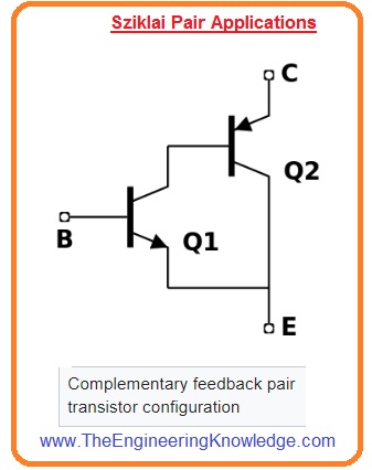
- In some applications sziklai pair work as a single transistor with a similar type as Q1 with a large current gain.
- The emitter of transistor Q2 does the role of a collector. So the emitter of transistor Q2 is denoted as C.
- The emitter of Q2 acts as the role of a collector. Hence, the emitter of Q2 is labeled “C” in the figure to the right.
- Similar to the normal applications the collector of transistor Q2 work as emitter and denoted as E.
- In Darlington, pair transistor resistance of one hundred ohms to one thousand ohms can be used between transistor Q2 emitter and base to increases turn off time.
So, friends, it is a detailed post about the Sziklai pair if you have any questions ask in comments. Thanks for reading.


