 Hello, friends, I hope all of you are enjoying your life. In today’s tutorial, we will discuss What is voltage Regulation. In the electrical engineering especially, parameters related to power, voltage regulation is the important factor, it is the measurement of the variation in the quantity of voltage at receiver and sending devices, its example is a transmission of voltage. This phenomenon tells us how we can maintain the capability of the power system to provide the same value of the voltage at different loads.
It is main factor which tells us how we can stable voltage in our system. In today’s post we will have look at its equation, working, introduction, and some other related terms. So, let’s get started with the What is voltage Regulation.
What is voltage Regulation
- The voltage regulation has no units it is the ratio between voltage values. Its formula is given here.
VR = [(Vnl)- (Vfl)]/ (Vfl)
Percent VR = [(Vnl)- (Vfl)]/ (Vfl) x 100
- In this formula.
- (Vfl) is the value of the voltage at full load.
- The transmission line which has 0 value of resistance and reactance is known as an ideal transmission line. Its percentage voltage regulation will be 0 due to the same value of voltage at no load and full load.
- So, the less value of voltage regulation is important because it tells that the transmission line is almost ideal which is beneficial for our power system.
Voltage Regulation in Transmission Lines
- The voltage variation exits in the transmission lines due to the impedance present at its sender and receiver point.
- The value of voltage varies during the transmission due to the resistance(R), inductance and capacitance offered by the line which is the fundamental behavior of any transmission line.
- Due to this effect, both values of voltage angle and its magnitude will vary passing through the line.
- To study the effect of the impedance on the transmission line we study three types of transmission lines.
- Short length line.
- Medium length line.
- Long length line
Short Line.
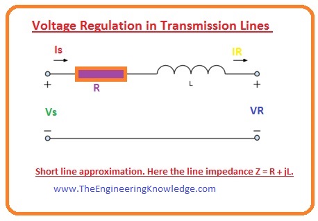
- In this calculation, the capacitance of the line of transmission is not considered and the resistance and reactance of the line convert into such circuitry which has the one resistor and inductor.
- Its equation is written here.
R + jL
- The current in the short line will be I = Is =IR
- Here the IR the receiving end current and Is is the sending end current.
Medium Length Line
- In this line we consider the shunt admittance of the line, generally capacitance, by spreading half value of admittance at the sender point and half at the receiver point.
- Such type of arrangements is also known as the pi (Π).
Long Length Line
- In this line, we consider the lumped (An impedance concerted in a solitary constituent rather than spread throughout the length of a transmission line) impendence and admittance and allocates them homogenously along the distance of the line.
- So, the long length lines need differential equations and outcomes should have high
- If we look at the equation of the voltage regulation which is given here.
VR = [(Vnl)- (Vfl)]/ (Vfl)
- In this equation, the (Vnl) is the voltage calculated at the receiver point when there is no load device at that point.
- The complete short line approximation is an open circuitry in this situation, and there is a current move in the open circuitry. so (I = 0 A) and the loss of voltage at the line can be fined by the ohm’s law.
Vline loss = I x Zline = 0
- The voltage at send point and receiver point will be similar.
- In the voltage regulation equation, the other factor Vfl is the voltage across the load which is linked at the receiving point of the line.
- In this equation the Vline loss = I x Zline will not be 0. So, the voltage at the sending point and the receiving will not be identical.
- So, the value of current can be found by using Ohm’s law by adding impedances of the load and transmission line.
I = Vs/(Zline+Zload)
- So voltage regulation at the full load can be given as.
VR,fl = Vs – (VsZline)/( Zline+ Zload)
Voltage Regulation Phasor Diagrams
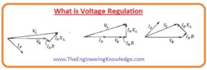
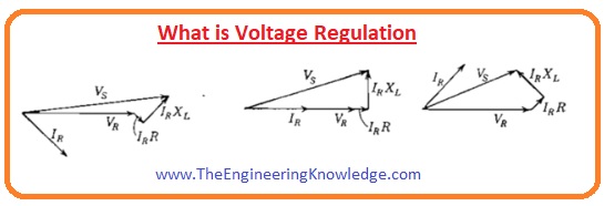
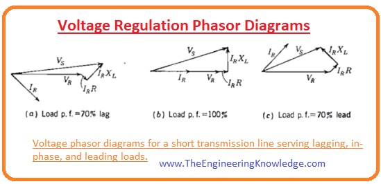
- In the below-given diagram there 3 p.fs values are described.
-
- (a) the load is inductor so the current lag at the receiver point.
- (b) in this situation, the load is the resistor so the current and the voltage at the receiver point are in the phase.
-
- (c) in this situation, the load is capacitive so the current leads the receiving voltage point.
- In all these situations the resistance present in the line drop such voltage which are in phase with the current.
- The reactance of the line drop such voltage which leads current by 900.
- These consecutive voltage losses are added to the voltage at the receiver point, moving back from (VR) to (VS) in the short line calculation circuitry.
Effect of the phase angle Current on the Voltage Regulation
- The above-given phase diagram tells that the in-transmission line the phase angle of current disturbs the value of voltage regulation.
- We discuss these three phasor diagrams one by one.
- As you can see that current in (a) diagram is lagging it increases the voltage at sending point as compared to the receiving point. The phase angle alteration amid sending and receiving points is minimalized.
- In (c) phasor diagram the current is leading so it will decrease the sending point voltage than the receiving point. so, the voltage illogically upsurges along the transmission line.
- In figure (b) the current is in phase its effect on the voltage of sending point and receiving point will be very less.
- In practice, almost all transmission has an inductive load, like motors, which we see everywhere.
- Due to the larger value of reactive power (Q) the line current lags behinds the voltage and the voltage regulation is considered by a reduction in voltage extent.
- In transporting a larger quantity of active power (P) to loads, a current is frequently in phase with the voltage.
- The VR in this situation is categorized by a lessening in phase angle than the magnitude.
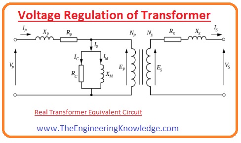
Voltage Regulation of Transformer
- The non-ideal elements of the transformer become a reason of the voltage variation when a current passes through them.
- In case when there is no load at the secondary of the transformer, the value of Vnl is given as
VS= V (NS/NP).
- Observing at the corresponding circuitry of a transformer and ignoring the shunt elements, as is a realistic calculation, we can refer all resistances and reactance to the secondary of the transformer and evidently understand that the Vs at no-load will certainly be specified by the ideal circuitry.
- In dissimilarity, when the transformer working at the full-load, a voltage loss happens at the resistance of the windings, producing Vt at the load to less than expected.
So friends that is the detailed post about the voltage regulation. I have written each and every parameter related to voltage regulation. If you have any further queries about this post ask in comments. See you in next post have a good day. Thanks for reading.



Very educative article, learned a lot. So glad I discovered your blog, and was able
to learn new things. Keep posting articles, it’s really valuable.
Best regards,
Thomassen Raahauge