Hello readers, welcome to the new post. Here we will learn about the Teensy 4.1 pinout, schematic symbol, specifications, and board s, and board layout. In the field of microcontrollers,gh-power Arduino based on NXP i.MX RT1062 ARM Cortex-M7 operates with 600 MHz features of overclocking. It is supported with Arduino IDE programming, also with many other Arduino libraries, and is easy to configure. Whether you are an electrical engineer or a professional embedded systems developer, learning Teensy 4.1’s schematic symbol, pinout, features, and board layout is important. In this post, we will learn the features of this best microcontroller, So let’s get started with the Teensy 4.1 pinout.
Introduction to Teensy 4.1
Teensy 4.1 is a high-power Arduino-supported microcontroller. It is based on the NXP i.MX RT1062 ARM Cortex-M7 operating at a 600 MHz frequency with features overclocked.
It is configured in a compact teensy board outline for simple embedding in projects and USD for solderless breadboards.
It has compatibility with the Arduino IDE programming structure with other Arduino libraries.
It comes with 1024 KB RAM, 7936 KB flash memory, and 4 KB EEPROM. There are 18 analog pins it has with 55 digital input and output pins on board; out of that, 35 pins are configured with pulse width modulation.
It supported the different communication protocols such as CAN, I2C, and SPI serial communication protocols.
As compared to the Teensy 4.0, the Teensy 4.1 comes with an ethernet controller and ethernet PHY chip. Just an RJ45 mag jack kit is needed to connect the Ethernet cable.
It also comes with an onboard D card slot for SD cards that makes it different than other Teensy boards.
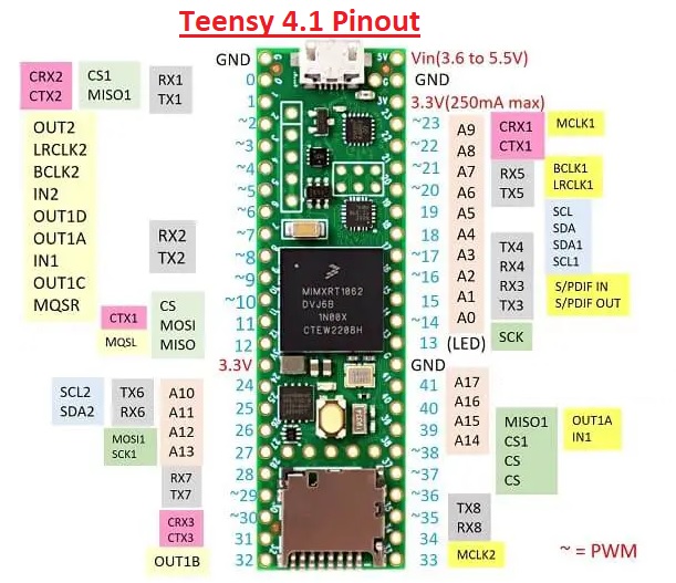
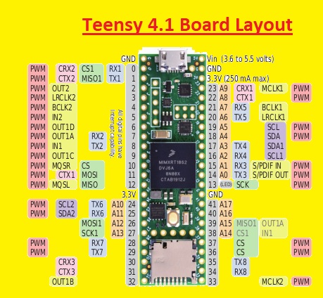
Teensy 4.1 Pinout
The Teensy 4.1 comes with 55 input/output signal pins. 42 can be access when used with a solderless breadboard.
Here is a Teensy 4.1 pinout:
| Pin | Name | Function |
| 0 | CS1 | Chip select for SPI1 |
| 1 | MISO1 | Master in/slave out for SPI1 |
| 2 | MOSI1 | Master out/slave in for SPI1 |
| 3 | SCK1 | Serial clock for SPI1 |
| 4 | 3.3V | 3.3V power supply output |
| 5 | GND | Ground |
| 6 | A0 | Analog input 0 |
| 7 | A1 | Analog input 1 |
| 8 | A2 | Analog input 2 |
| 9 | A3 | Analog input 3 |
| 10 | A4 | Analog input 4 |
| 11 | A5 | Analog input 5 |
| 12 | A6 | Analog input 6 |
| 13 | A7 | Analog input 7 |
| 14 | A8 | Analog input 8 |
| 15 | A9 | Analog input 9 |
| 16 | A10 | Analog input 10 |
| 17 | A11 | Analog input 11 |
| 18 | A12 | Analog input 12 |
| 19 | A13 | Analog input 13 |
| 20 | LED1 | Red LED |
| 21 | LED2 | Green LED |
| 22 | LED3 | Blue LED |
| 23 | SW1 | Push button |
| 24 | 13 | Digital input/output 13 |
| 25 | 12 | Digital input/output 12 |
| 26 | 11 | Digital input/output 11 |
| 27 | 10 | Digital input/output 10 |
| 28 | 9 | Digital input/output 9 |
| 29 | 8 | Digital input/output 8 |
| 30 | 7 | Digital input/output 7 |
| 31 | 6 | Digital input/output 6 |
| 32 | 5 | Digital input/output 5 |
| 33 | 4 | Digital input/output 4 |
| 34 | 3 | Digital input/output 3 |
| 35 | 2 | Digital input/output 2 |
| 36 | 1 | Digital input/output 1 |
| 37 | 0 | Digital input/output 0 |
| 38 | CAN0_RX | CAN bus 0 receive |
| 39 | CAN0_TX | CAN bus 0 transmit |
| 40 | CAN1_RX | CAN bus 1 receive |
| 41 | CAN1_TX | CAN bus 1 transmit |
| 42 | I2C1_SDA | I2C bus 1 serial data |
| 43 | I2C1_SCL | I2C bus 1 serial clock |
| 44 | I2C2_SDA | I2C bus 2 serial data |
| 45 | I2C2_SCL | I2C bus 2 serial clock |
| 46 | I2S0_TXD0 | I2S bus 0 transmit data 0 |
| 47 | I2S0_TXD1 | I2S bus 0 transmits data 1 |
| 48 | I2S0_TXWS | I2S bus 0 transmit word select |
| 49 | I2S0_SCK | I2S bus 0 serial clock |
| 50 | I2S0_RXC | I2S bus 0 receives a clock |
| 51 | I2S0_RXD0 | I2S bus 0 receives data 0 |
| 52 | I2S0_RXD1 | I2S bus 0 receives data 1 |
| 53 | SW2 | Push button |
| 54 | 3.3V | 3.3V power supply output |
| Pin Number | Pin Name | Description |
| 1 | 3.3V | Provides a 3.3V power supply to external devices. |
| 2 | GND | Ground reference for the microcontroller. |
| 3 | VIN | Input voltage for external power supply. |
| 4 | 0 | General-purpose digital input/output pin. |
| 5 | 1 | General-purpose digital input/output pin. |
| 6 | 2 | General-purpose digital input/output pin. |
| 7 | 3 | General-purpose digital input/output pin. |
| 8 | 4 | General-purpose digital input/output pin. |
| 9 | 5 | General-purpose digital input/output pin. |
| 10 | 6 | General-purpose digital input/output pin. |
| 11 | 7 | General-purpose digital input/output pin. |
| 12 | 8 | General-purpose digital input/output pin. |
| 13 | 9 | General-purpose digital input/output pin. |
| 14 | 10 | General-purpose digital input/output pin. |
| 15 | 11 | General-purpose digital input/output pin. |
| 16 | 12 | General-purpose digital input/output pin. |
| 17 | 13 | General-purpose digital input/output pin. |
| 18 | 14 | General-purpose digital input/output pin. |
| 19 | 15 | General-purpose digital input/output pin. |
| 20 | 16 | General-purpose digital input/output pin. |
| 21 | 17 | General-purpose digital input/output pin. |
| 22 | 18 | General-purpose digital input/output pin. |
| 23 | 19 | General-purpose digital input/output pin. |
| 24 | 20 | General-purpose digital input/output pin. |
| 25 | 21 | General-purpose digital input/output pin. |
| 26 | 22 | General-purpose digital input/output pin. |
| 27 | 23 | General-purpose digital input/output pin. |
| 28 | 24 | General-purpose digital input/output pin. |
| 29 | 25 | General-purpose digital input/output pin. |
| 30 | 26 | General-purpose digital input/output pin. |
| 31 | 27 | General-purpose digital input/output pin. |
| 32 | 28 | General-purpose digital input/output pin. |
| 33 | 29 | General-purpose digital input/output pin. |
| 34 | 30 | General-purpose digital input/output pin. |
| 35 | 31 | General-purpose digital input/output pin. |
| 36 | VBAT | Battery voltage input for real-time clock. |
| 37 | VUSB | USB power input when connected to a computer. |
| 38 | GND | Ground reference for USB and other circuits. |
| 39 | PTE0/ADC0 | Analog input 0 and general-purpose digital I/O. |
| 40 | PTE1/ADC1 | Analog input 1 and general-purpose digital I/O. |
| 41 | PTE24 | General-purpose digital input/output pin. |
| 42 | PTE25 | General-purpose digital input/output pin. |
| 43 | AREF | Analog reference voltage for ADC. |
| 44 | GND | Ground reference for analog circuits. |
| 45 | A10 | Analog input 10 and general-purpose digital I/O. |
| 46 | A11 | Analog input 11 and general-purpose digital I/O. |
| 47 | A12 | Analog input 12 and general-purpose digital I/O. |
| 48 | A13 | Analog input 13 and general-purpose digital I/O. |
| 49 | A14 | Analog input 14 and general-purpose digital I/O. |
| 50 | A15 | Analog input 15 and general-purpose digital I/O. |
| 51 | A16 | Analog input 16 and general-purpose digital I/O. |
| 52 | A17 | Analog input 17 and general-purpose digital I/O. |
| 53 | A18 | Analog input 18 and general-purpose digital I/O. |
| 54 | A19 | Analog input 19 and general-purpose digital I/O. |
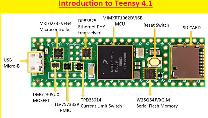
Teensy 4.1 Board Layout
The Teensy 4.1 board layout can seen here
MCU
The MCY in the Teensy 4.1 board is made by the MX RT1060 processor that comes with NXP’s advanced implementation of the Arm Cortex-M7 core. Its working speed is 600 MHz to offer high CU working and the best real-time response.
On-chip RAM exists for the MX RT1060 processor, which is one megabyte. The first 512 KB can be used for general-purpose on-chip RAM, and the 2nd 512 KB is used for general-purpose on-chip RAM.
Microcontroller
It is a secondary microcontroller that exists on the Teensy 4.1 board. It enhances the efficiency and operation of the board. It comes with a small size and energy-efficient ARM Cortex-M0+ 32-bit performance. Main features of controllers are
- Its run power use is 36 A/MHz low in run mode.
- Statue power use is 2 microamperes with full state retention and 4 μs wakeup.
- Ultra-efficient Cortex-M0+ processor running at up to 48 MHz
- It has 32 KB flash and 4 KB RAM.
Transceiver
It is a low-power Ethernet physical layer transceiver. It supported the 150 meters with the use of CAT5e cable.
SD CARD
There is an SD card slot exit for connecting the SD card.
MOSFET
It is a P-Channel Enhancement Mosfet. This transistor is high-power efficiency power management through reducing on-state resistance during maintaining switching operation.
Regulator
It is a low dropout regulator (LDO). TLV757P is made for different uses with an input voltage range of 1.45 to 5.5 volts. For supporting lower core voltage of modern MCU devices, it comes in a fixed output voltage range of 0.6 to 5 volts for reducing the cost and size of the board.
TPD3S014
TPD3S0x4s is an integrated device that has features of a current-limited load switch and a two-channel transient voltage suppressor based on an ESD protection diode array for USB interfaces.
Serial Flash Memory (W25Q64JVXGIM)
It is external serial flash memory employed with n MCU. It offers external flash memory to the board.
Teensy 4.1 Specifications
- i.MX RT1062 ARM Cortex-M7 running at 600 MHz.
- 1MB (1024K) RAM (512K tightly coupled)
- 8MB FLASH
- 2 QSPI chip locations to add up to 16MB PSRAM or 8MB PSRAM and 16MB FLASH
- 10/100 Mbit DP83825 PHY Ethernet header (Non-NE version only)
- USB host pins
- Micro SD Socket
- 2 USB ports, both 480 Mbit/sec, can be any device type.
- 3 CAN Bus (1 with CAN FD)
- 3 I2C, all with 4-byte FIFO
- Cryptographic Acceleration
- Random Number Generator
- Built-in RTC for date/time
- Dynamic clock scaling
- 8 serial ports, all with 4-byte FIFO
- 32 general-purpose DMA channels
- 35 PWM-capable pins
- 55 digital I/O, all interrupt capable
- 42 breadboard-friendly I/O pins
- 2 I2S Digital Audio
- 1 S/PDIF Digital Audio
- 1 SDIO (4-bit) native SD
- 3 SPI, all with 16-word FIFO
- 18 analog input pins with 2 12-bit ADCs on-chip
- True 64-bit floating point via FPU hardware
- Programmable FlexIO
- Small size is perfect for embedding or use with solderless breadboards.
- 3.3V operation and I/O compatibility
- Pixel Processing Pipeline
- Peripheral cross-triggering
- Power On/Off management
- Compatible with Arduino IDE and many libraries
- Works with Windows, Mac OS X, and Linux
How to power the Teensy 4.1?
USB
- Teensy is powered with a PC or USB hub through a USB cable. The USB power is given at the VUSB pin, which is connected to VIN.
VIN Pin
- If not using USB power, 5V power can be connected with a VIn pin. Since Vin and VUSB are connected and power is not given to Vin with the use of USB.
3.3V
- The Teensy 4.1 comes with a voltage regulator that decreases five volts VUSB/VIN to 3.3V for normal use with the main processor and other components. The 3.3 V pin can be used to power more circuits. The highest recommended voltage of 3.3 volts is 250 mA.
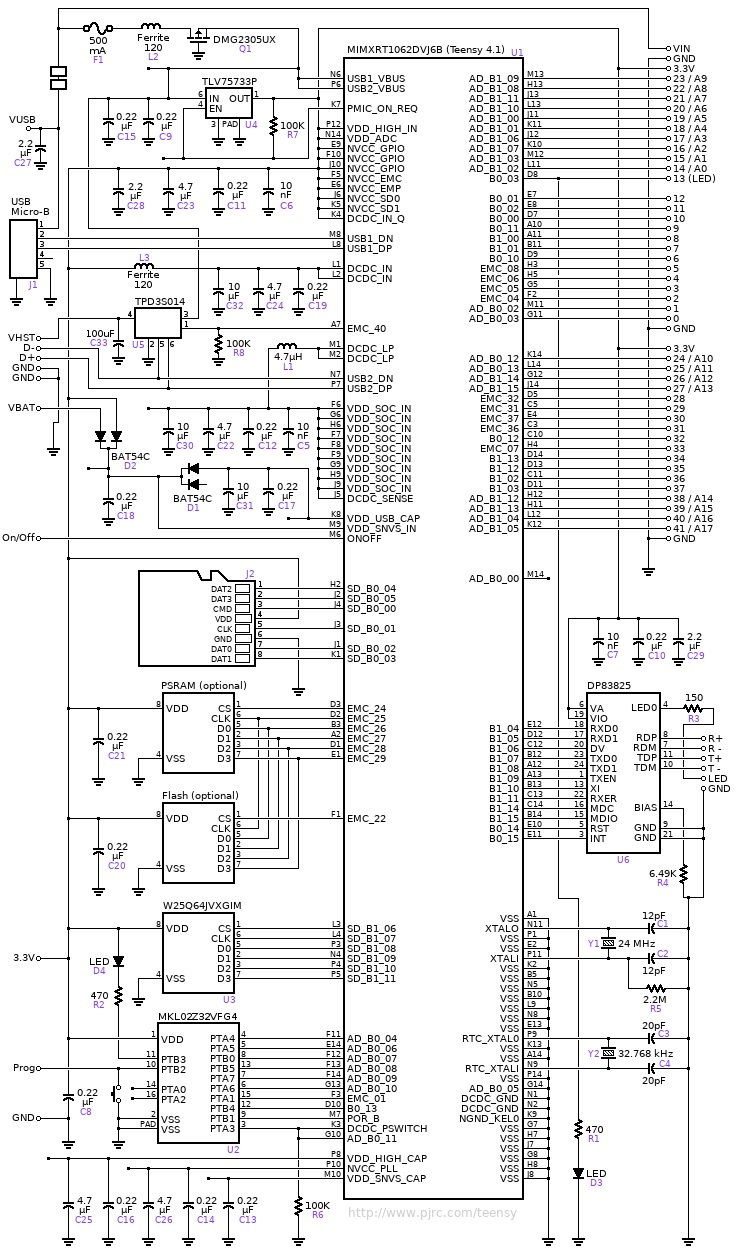
Teensy 4.1 Schematic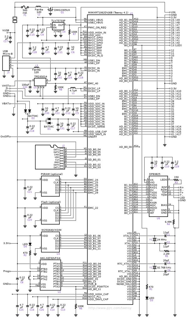
Teensy 4.0 vs Teensy 4.1
| Feature | Teensy 4.0 | Teensy 4.1 |
| Processor | IMXRT1062DVL6 | IMXRT1062DVJ6 |
| Flash memory | 1984 kbytes | 7936 kbytes |
| EEPROM | 1080 bytes | 4284 bytes |
| Digital I/O | 40 pins | 55 pins |
| Breadboard I/O | 24 pins | 42 pins |
| Analog Input | 14 pins | 18 pins |
| Total PWM outputs | 26 pins | 31 pins |
| Serial Ports | 7 | 8 |
| Ethernet | no | 1 |
Read also:
- Introduction to NXP LPC Microcontrollers
- 10 Types of Microcontrollers: A Comprehensive Guide for Beginners
- Introduction to MG82F6D17 Microcontroller
- W78E052DDG Microcontroller: Overview, Features, and Applications
- Introduction to STM8 Microcontroller
- Difference Between Microprocessor and Microcontroller
FAQs:
The Teensy 4.1 is the Teensy 4.1?
Teensy 4.1 is a high-power Arduino-supported microcontroller. It is based on the NXP I. MX RT1062 ARM Cortex-M7 running at 600 MHz.
It is a compact teensy board for easy embedding with different projects or used for solderless breadboards.
Q: What are the advantages of the Teensy 4.1 over other microcontroller boards?
It is a high-performance development board that enhances the power of the ARM Cortex-M7 processor operating at 600 MHz, a floating-point math unit (64 & 32 t (64 & 32 bits). 1024K RAM, 4K of emulated EEPROM, 7936K Flash, 55 digital input/output pins, 3 I2C ports, an SD card slot, 3 SPI busses, and port Ethernet 10/100 Mbit, RTC for date
What are the applications of Teensy 4.1?
its common uses are
- Audio
- Cycle counter
- Flight simulator
- Interval timers
- Memory expansions
- MIDI
- PWM timers
- Software timing
- SysTick
How do I get started with the Teensy 4.1?
First of all, connect the new Teensy with a USB cable. Just plug the Teensy board into the USB port to start. All Teensy boards come with an LED blink program pre-loaded. Check Orange LED; it blinks slowly, 1 second on, 1 second off.
Q: What are the advantages of Arduino over other microcontrollers??
- Easy to use and accessible
- Open source and for everyone to use
- It comes with many libraries and shields.
- It has support for different components.
- cost-effective and affordable.
Q You can buy a Teensy 4.1 board?
A: The Teensy 4.1 board can be bought from the official PJRC website or other online retailers.
Is Teensy 4.1 a substitute for other development boards?
- Yes, it is used as a replacement for development boards such as the Arduino Uno or the Raspberry Pi.
- But it is more powerful and versatile than these boards, so it is not for all projects.
- Such as if anyone making a project, such as LED blinking, can be good with the use of a less costly board, such as the Arduino Uno.
Is Teensy 4.1 better for audio projects?
- it is best to use for audio DAC and ADC. It also comes with different peripherals and is best for audio projects, like I2S and SPDIF.
How to connect Teensy 4.1 with Ethernet?
- The Prototyping System for Teensy 4.1 comes with an ethernet header on Teensy 4.1. It makes a connection through a 6-pin extended reach male header that connects with the female header at the lower part of the Teensy 4.1.