

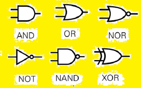
 Hello, readers welcome to the new post. Here we will discuss Logic Gates. Digital circuits are considered as the building block of modern computing and communication system applications. Digital circuits are a combination of logic gates that uses binary data to perform differnt operations. There are 7 types of logic gates used in digital circuits that are NOT, NAND, NOR, AND, OR, XOR, and XNOR. These gats combined to make complicated circuits which used to process data in differnt functions.
In this post, we will discuss digital circuits and their truth tables in detail. So let get started
Table of Contents
- Introduction
- What are Logic Gates?
- AND Gate
- OR Gate
- XOR Gate
- NOT Gate
- NAND Gate
- NOR Gate
- XNOR Gate
- Applications of Logic Gates
- Building Digital Circuits with Logic Gates
- Advantages and Limitations of Logic Gates
- Conclusion
- FAQs
1. Introduction to Logic Gates
- Logic gates are the core components of digital circuits that are used to perform different operations in differnt fields like computers, telecommunication, and industrial controls.
- Logic gates operate based on a Boolean function which gets one or more binary inputs and generates binary output based on input.
- Through a combination of differnt gats high-level circuits designed that solved the complicated operations
2. What are Logic Gates?
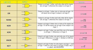
- The logic gate is an electronic module that performed logic operations through the use of one or more than one binary number
- The output of logic gates is based on the combination of inputs provided on the base of the logic function that it used.
- The 2 binary numbers One and Zero denotes Boolean algebra values as true or false.
- The inputs of the truth table are drawn in form of the truth table and the output obtained through the use of inputs
3. AND Gate
- It is a type of logic gate that provides a true output if both inputs are true. If any input is zero its output will be zero.
- Its symbolic representation is like a triangle with a circle at the output side and a Boolean function represented by this gate defined through logical expressions A and B which are its inputs.
- Here you can see the truth table of And the gate
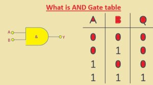
| Input A | Input B | Output |
|---|---|---|
| 0 | 0 | 0 |
| 0 | 1 | 0 |
| 1 | 0 | 0 |
| 1 | 1 | 1 |
4. OR Gate
- The OR gate produced the true output if one input is true or 1. for other options give a false result
- The symbolic representation of the OR gate is a curved line having a circle at the output side and the Boolean function used by this gate is denoted through expressions A and B as input
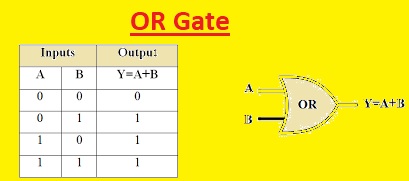
| Input A | Input B | Output |
|---|---|---|
| 0 | 0 | 0 |
| 0 | 1 | 1 |
| 1 | 0 | 1 |
| 1 | 1 | 1 |
5. XOR Gate
- The XOR gate is a logic gate that generates true output if it is differnt values. For other cases give false results.
- The symbolic representation for the XOR gate is a curved line having a diagonal line at the output side and the Boolean function it used is denoted as A xor B
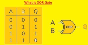
| Input A | Input B | Output |
|---|---|---|
| 0 | 0 | 1 |
| 0 | 1 | 0 |
| 1 | 0 | 0 |
| 1 | 1 | 0 |
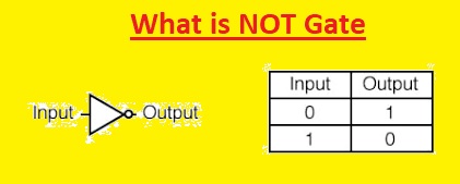
6. NOT Gate
- The NOT gate generates true results if the input is false and vice versa. The symbolic representation of NOT gate is a triangle having a small circle at the output side and the Boolean function it used is denoted as the logical expression “not A”, A is input
| Input | Output |
|---|---|
| 0 | 1 |
| 1 | 0 |
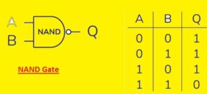
7. NAND Gate
- The NAND gate is a logic gate that makes false output if all inputs are one or true. For other options, it produces true output
- The symbolic representation of the NAND gate is a triangle having a small circle at the output side and a curved line
- The input side and Boolean function implemented by the logical expression is “not (A and B)”
- Its table can see here
| Input A | Input B | Output |
|---|---|---|
| 0 | 0 | 1 |
| 0 | 1 | 1 |
| 1 | 0 | 1 |
| 1 | 1 | 0 |
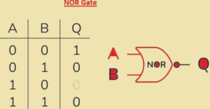
8. NOR Gate
- The NOR gate is a logic gate that makes a false result if any one inputs is true and for other cases, it makes the true output
- The symbolic representation of NOR gate is a curved line having a small circle at the output side and the Booleans function is represented by this gate with logic expression is “not (A or B)”,
-
A B Output 0 0 1 0 1 0 1 0 0 1 1 0
9. The XNOR Gate
- The XNOR gate is a logic gate that makes true results if its inputs are the same and the output is faulty is they are not same.
- The symbolic representation of the XNOR gate is a curved line having a small circle at the output side and a diagonal line at the input side.
- The Boolean function that is implemented by the logic expression is “not (A xor B)”
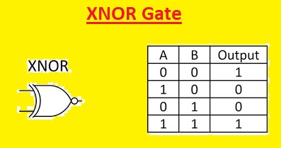
| Input A | Input B | Output |
|---|---|---|
| 0 | 0 | 1 |
| 0 | 1 | 0 |
| 1 | 0 | 0 |
| 1 | 1 | 1 |
10. Logic Gates Applications
- Logic gates come with differnt applications like solutions of arithmetic operations, digital circuits, data storing and retrieval control systems, etc.
- For example, simple adder circuitry can be designed through the use of AND, OR, and XOR gate, and for flip-flop circuits, NAND and NOR gates is used
11. How to make Digital Circuits with Logic Gates
- Digital circuits are created by joining the differnt types of logic gates in certain ways to do required operations.
- This process uses circuit design, choosing accurate gates, and wiring these components to apply logical functions
- The resultant circuits can be tested through the use of simulation software or through physics components analysis of connection
12. Advantages and Limitations of Logic Gates
- Logic gates provide many benefits than other analog circuits such as accuracy reliable operation and easy integration process
- With that, they also have some limitations like limited operating frequency, power use, and chances to affect through noise and interface
13. Conclusion
Finally, logic gates are the fundamental components of digital circuits that carry out straightforward operations on binary data. And, OR, XOR, NOT, NAND, NOR, and XNOR are the seven types of logic gates that can be combined to create intricate circuits that process information in a variety of ways. In comparison to analog circuits, logic gates offer several advantages and have numerous applications in digital circuits. However, when designing and utilizing digital circuits, they also have limitations that must be taken into account.
14. FAQs
- What is the use of a logic gate?
- it is an electronic device that does different logic operations based on the input provided. It implements a digital circus for processing the information
- How many types of logic gates?
- There are 7 main types of logic gates: AND, OR, XOR, NOT, NAND, NOR, and XNOR these gates can join with each other to solve complicated circuits
- What is the difference between an AND gate and OR gate?
- The AND gate generates a true result for bot inputs that are true and or gate generates true if anyone’s input is true
- Can logic gates be used in analog circuits?
- No, these gates are used for logic circuits
- What are the limitations of logic gates?
- Its limitation is operating frequency, power consumption, and susceptibility to noise and interference.

