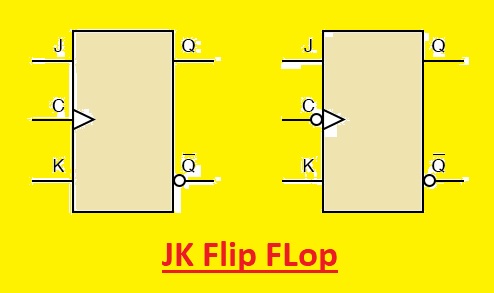
 Hello, readers welcome to the new post. In this lesson, we will learn Introduction to JK Flip Flop. JK flip-flop is a commonly used type of flip-flop and is used in different applications as universal flip-flop circuitry. Its function is like the RS flip flop having the same SET and REST inputs. The difference is that JK flip flop not supported the invalid states of RS Latch. Its name JK flop is given due to its creator Jack Kilby
In this post, we will learn its circuit, truth table, and some other parameters. So let’s get started with Introduction to JK Flip Flop.
Introduction to JK Flip Flop
- The JK Flip flop is a bi-state single-bit memory component that comes with a single input or CLK pinout, two pinouts for data J and K, and two output pins (Q and Q̅). It can be triggered through the leading edge of a clock or the trailing edge of a clock and can be positively or negatively triggered.
- The simplest SR NAND flip-flop circuitry provides some benefits and works through the use of sequential logic circuits with some issues.
- Set =0 and Reset=0 or S=R=) must not use for SR NAND circuits.
- If Set or Reset changes with EN input is a high state then accurate latching can not be obtained.
- To resolve these issues for SR NAND JK FLIP FLOP was created.
- JK FLIP FLOP has two inputs J and K. The sequence working of the JK FLip flop is like the SR flip flop having the same values of Set and Reset inputs.
- The basic difference is that the JK flip-flops do not have invalid inputs. JK Flip flop is a gated SR flip flop that has additional clock input circuitry to avoid the invalid input state which exists for inputs S and R that are equal to a logic level one. This additional clock input JK flip flop comes with four options of input combinations, Logic 1, Logic 0, no change, and toggle. The symbolic representation of JK flip is like the SR Bistable Latch
JK Flip-flop Circuit
- In the below figure, we can see that the internal structure of the JK flop is created through the use of AND gates and NOR gates.
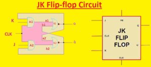
- In this circuit, we can see that output Q is logically AND configured with input K and a clock signal, and output Q̅ is AND configured with J input and a clock signal.
- The output of A1 is given to input NOR gate N1 as a1 and the input of b1 is given to output Q̅. Like this second NOR gate, N2 also has two inputs a2 and b2, and that are outputs of A2 and output Q
- Let’s suppose that we have J = K = 0, Q = 0, and Q̅ = 1. So take the positive edge of the first clock pulse at CLK pinout of the flip flop. That causes the a1 and a2 = . The output of N1 NOR gate is zero since a1 is zero and Q̅ = 1. The output of N will be one since a2 is 0 and Q is 0.
- So we have Q = 0 and Q̅ = 1.
- So if we suppose another condition that is J = K = 0, Q = 1 and Q̅ = then a1=a2=0 which results in Q=1 and Q̅ = 0. That indicates the condition of flip-flop outputs Q and Q̅ remains not changed for J = K = 0 condition
- Let take other condition that J = 0, K = 1, Q = 0 and Q̅ = 1. so we gets a1=a2=0 that results in Q=0. With that condition if Q and Q̅ are 1 and 0 then a1=1 and a2=0 that results in Q = 0
- That indicates that if J = 0 and K = 1, then flip flop resets (Q = 0 and Q̅ = 1).
- Now tale other condition J = 1, K = 0, Q = 1 and Q̅ = 0, then a1 = a2 = 0 which results in Q = 1 (and thus Q̅ = 0). In the same condition if Q = 0 and Q̅ = 1, then a1 = 0, a2 = 1 results to Q̅ = 0 and the value of Q is one. It indicates that for J=1 and K=0 flip flop output will be Q = 1 and Q̅ = 0.
- Like this for condition J = 1, K = 1, Q = 1 and Q̅ = 0 one gets a1 = 1, a2 = 0 and Q = 0 and if Q changes value o zero and Q̅ to 1, then a1 = 0, a2 = 1 which forces Q̅ to 0 and hence Q to 1.
- It defines that for condition J = K = 1 flip flop outputs toggle indicates that Q varies from zero to one or one to zero and these variations are shown at output pin Q̅ accordingly.
JK Flip Flop Truth Table
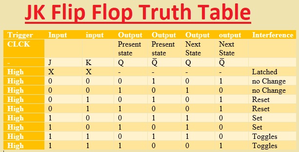
- The truth table of JK flip flop is created here
| Trigger | Input | input | Output | Output | Output | output | Interference |
| CLCK | Present state | Present state | Next State | Next State | |||
| – | J | K | Q | Q̅ | Q | Q̅ | |
| High | X | X | – | – | – | – | Latched |
| High | 0 | 0 | 0 | 1 | 0 | 1 | no Change |
| High | 0 | 0 | 1 | 0 | 1 | 0 | no Change |
| High | 0 | 1 | 0 | 1 | 0 | 1 | Reset |
| High | 0 | 1 | 1 | 0 | 0 | 1 | Reset |
| High | 1 | 0 | 0 | 1 | 1 | 0 | Set |
| High | 1 | 0 | 1 | 0 | 1 | 0 | Set |
| High | 1 | 1 | 0 | 1 | 1 | 0 | Toggles |
| High | 1 | 1 | 1 | 0 | 0 | 1 | Toggles |
Master-Slave JK Flip-flop
- The master-slave flip flop removes all timing issues through the use of two SR flip flops making a series combination. One flip flop work as the master that triggers on the leading edge of the clock pulse and the other operates as a slave that triggers on the falling edge of the clock pulse. That makes two configurations master and slave that enabled through an opposite half cycle of the clock signal
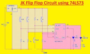
- The TTL 74LS73 is a dual JK flip flop integrated circuit that has 2 JK bistable in a single chip making enable single or master slaves toggle flip flops. Other Ics like 74LS107 Dual JK flip flop through clear the 74LS107 dual positive edge triggered JK flip flop and 74LS107 dual negative triggered flip flop with preset and clear inputs
JK Flip Flop Circuit using 74LS73
What is meant by JK flip-flops?
- JK flip flop is a flip flop that has some logic gates in front of D- The flip flop. The JK flip flop is known as a universal flip flop since its operation as SR flip flop, D flip flop
What are the types of flip-flops?
- S-R Flip Flop.
- J-K Flip Flop.
- T Flip Flop.
- D Flip Flop.
Which IC is used in JK flip-flop?
- The 7476 is master-slave JK and 74LS76 is negative edge triggered JK flip flop. Both ICs configured with similar pinouts
What is the characteristics of JK flip-flop?
- The JK flip-flop is an SR flip-flop having additional feedback. he invalid state is removed through user feedback that selects and enables one of the two set/reset inputs so that an active signal cannot be sent to the multivibrator circuitry
Is JK flip-flop synchronous or asynchronous?
- Flip-flops may have synchronous inputs, asynchronous inputs, or both.
Where is JK flip-flop used?
- JK flip flop makes circuitry toggle among two states and is mostly used in the shift register, counter and PWM, and computer circuits
That is all about the JK Flip Flop all details has explained. If you have any queries ask here

