 Hi fellows I hope you all are having fun in your daily life. In today’s post, we will have a detailed look at Introduction to PIC16F877. This is a basic type of microcontroller which is most commonly used. This module provides different types of features such as less expensive, reliable, easy to access, and better quality over other modules.
It is the best option for such an application that uses different types of machines like motors, measuring instruments, and different engineering projects. This controller has all the important features that usually exist in other controllers. In today’s post, we will have a detailed look at its working, operation, pinouts, and some other parameters. So let’s get started with the introduction to Introduction to PIC16F877.
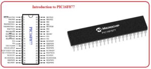
Introduction to PIC16F877
- The PIC16F877 controller belongs to the PIC family of the controller. it is an eight-bit controller which was created by the Microchip.
- There are 3 different types of packaging structures in which it usually comes first one is PDIP (Plastic Dual In-line Package), the second one is PLCC (Plastic Leaded Chip Carrier), and the third one is Quad Flat No-leads package.
- In its packaging arrangements, there are forty pinouts and in QFN and PLCC, there are forty-four pinouts.
- There is EEPROM (electrically erasable programmable read-only memory) which has a storage space of two fifty-six bytes, with that there is random access memory with a space of three sixty bytes created on this board.
- At this board, there is a timer, analog to digital converter, and some other important elements are assembled.
Features of PIC16F877
- These are some important features of this board which is mentioned here.
- This board comprises of the central processing unit which is based on RISC architecture.
- Its input clock has two megahertz frequencies.
- There are normally forty pinouts is created at this board.
- Out of forty, there are thirty-three pins are used as input and output pins.
- Six pins are used as analog input pins.
- There is a flash memory of fourteen-kilo bytes is created on this board.
- This board is incorporated with static ram having a space of three sixty-eight bytes.
- There is EEPROM of having space of two fifty-six is created on this board.
- like other controllers, 3 timers are assembled on this board which are timer, 1, 2, and 3.
- The voltage range for which it operates is four to 5.5 volts.
- The frequency of the oscillator to the twenty megahertz.
- The creator of this controller is Microchip.
- There are five ports are created on this board which are A, B, C, D, and E.
- Two plus width modulations exist on this board.
- Analog to digital converter of ten bits with eight-channel is used at this board.
- There is a watchdog timer for observing the operation of different parts is exists at this board.
- The commonly used protocol for communication is UART, SPI, I2C, and ICSP.
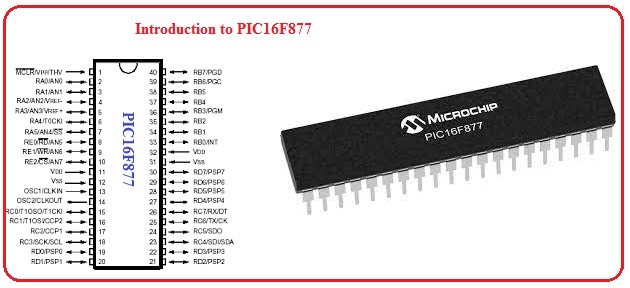
Pinout of PIC16F877
- The pinouts of this board are described here with the details.
MCLR’VPP
- This pinout is used as a master clear pinout.
RA0AN0
- This pin is used as a digital input and output pinout.
RA1AN1
- This pin functions as a digital input and output pinout.
RA2AN2VREF-
- This pinout operates as digital input and output pins and also as reference pinout.
RA4T0CKI
- This pin is a digital input and output pin and operates as the exterior clock input.
RA5AN4SS’
- This pinout is operated as digital input and output pin and used for the selection of SPI protocol.
RE0AN5RD
- That is also digital input and output pinout and operates input for parallel slaves device.
(AN0 TO AN7)
- These pins are used for the connection of analog inputs with the board.
TX and RX
- These pins are used as transmitters and receivers.
SCK
- Through this pinout, a serial clock input signal is given to the board.
SCL
- At this pin, SPI and I2C protocols are provided.
DT
- At this pin, synchronous data are provided.,
CK
- This pin is used as a connection of synchronous clock input.
SDO
- Through this pin output of the serial peripheral interface is taken out.
SD1
- The data input of spi is given at this pin.
Specs of PIC16F877
Power saving STOP mode
- This mode helps to stop PIC16F877 without disconnecting from the circuit.
High-speed PWM
- This module produces about 256 levels at the output and comes with a built-in clock programmable prescaler.
internal voltage regulator
- This internal voltage regulator comes in an input-output circuit and integrated oscillator
Analog to digital converter
- it comes with a resolution value of 12bits and has features to transform about 4 analog input channels at the same time
External interrupts
- It uses external interrupts for the sleep mode of any device
PIC1687 Input/Output Port

PORT A
- This port works as an analog input port, digital input, or output and is also used as PWM output. In this port, 6 pins are from PIn2 to PIN 7 that are denoted as RA0 to RA5 on the controller
PORT B
- This port performs the digital input, analog input functions, timer output comparison, and PWM input. In this post, there are a total of 8 pins that are from PIN33 to PIN 44 and denoted as RBO to RB7
PORT C
- In port, 8 pins are pIN 15 to PIn18 and pin 23 to 26. These pins are denoted as RD0 to RD7. Their main function is
- Digital input
- Analog input and output timer
PORT E
- It has 3 pins from pin 8 to pin 10 and is denoted as RE0 to RE2.
The ports of this controller are configured with 2 registers. Such as Port C comes with PORTC and TRISC registers. TRISC registers to define that is port is input or output.
Faqs
What is the PIC16F877 microcontroller?
- The PIC16F877 is an 8-bit controller and comes with 8K program space, 33 input-output lines, and eight ten-bit ADC pins. It comes with the highest speed about 20Mhz and is programmed in the circuit.
What is PIC16F877 used for?
- PIC16F877 is used for different embedded projects such as Bank security system Home Automation system
What is the difference between PIC16F877A and PIC16F877?
- 16F877A is new port and flash programming is high speed as compared to 16F877. For ICD they are in the same configuration and A shows the high-speed program and uses A type of projects.
What is interrupt in PIC16F877?
- The interrupt is a special component that stops the controller from performing any operation and is used to perform certain taks like Interrupt Service Routine (ISR) or Interrupt Handler.
What is the architecture of 16F877 PIC microcontroller?
- PIC16f877 comes with 20 internal interrupts and 3 external interrupts sources that are configured with different devices such as ADC, USART, Timers, etc. PIC comes with 5 ports ports A to E.
Which software is used for PIC16F877A?
- Microchip PIC16F877 comes with 8 K-bit word flash memory unit and is programmed with the use of C or assembly language. We can use MPLAB X IDE (Integrated Development Environment), that comes with an assembler. XC8 is also used that is a C compiler for Microchip’s 8-bit compilers.
Is PIC microcontroller a PLC?
- The PIC controller is a single-chip computer since it is small in size low cost and reliable in nature. The PLC is a complete design that uses different chips and larger sizes and high cost.
Which is better PIC or 8051?
- 8051 micro-controller slow working device as compared to PIC controller. PIC controller high speed devices
Why Arduino is better than PIC microcontroller?
- The Arduino is considered as development while PIC is a chip. If there is make comparsion between board to board or chip with chip they are the same prices but Arduino is easy to use for beginners
What are the features of PIC16F877?
- 256 bytes of EEPROM data memory
- self-programming
- an ICD
- 8 channels of 10-bit Analog-to-Digital (A/D) converter
- 2 additional timers
- 2 capture/compare/PWM functions
- synchronous serial port
How many pins are in PIC16F877?
- 40 pins
Is PIC microcontroller RISC or CISC?
- PIC microcontroller has features to use 38 clock cycles. The RISC is double high speed as compared to CISC modules. CISC devices get high execution for single working and not support parallel processing and pipelining of instruction
Which microcontroller is better PIC or AVR?
- PIC required different clock cycles for single instructions. The AVR applies instructions on one clock cycle. PIC comes with small fixed hardware configuration. The AVR comes with a stack pointer that can use available RAM
So friends that is a detailed post about PIC16F877 I tried my level best to make this post simple for you. If you have any further query ask in the comments. thanks for reading, Have a good day,