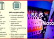
Hi, readers welcome to our next interesting post. In today’s post, we will look at the Introduction to PIC Microcontroller. The PIC stands for peripheral interface microcontroller, created in 1993 by the General Instrument Microcontroller. For the control and performance of the different operations, it is programmed by the different software. This controller comprises different electronic devices such as smartphones, medical instruments, and acoustic devices.
Different types of PIC controllers exits which are PIC16F84 to PIC16C84. In 1998 Microchip created the PIC16F84 which comprises programmable flash memory and in 2001 erasable model of this controller was developed. Nowadays there are numerous PIC controller exits in the market that provide different features such as serial communication, and UART. In today’s post, we will have a detailed look at its working, pinout, operation, and some other related parameters. So let’s get started with Introduction to PIC Microcontroller.
Introduction to PIC Microcontroller
- The PIC which reads as the ‘pick’ belongs to the group of microcontrollers created by Microchip technology and followed by the PIC1650.
- Firstly the word PIC is referred to as a peripheral interface controller and now stands for the programmable intelligent computer.
- Older types of PIC comprise ROM or field programmable EPROM to store data and some models have an erasable memory unit.
- Currently used models of PIC use flash memory to store data and also can get reprogrammed through itself.
- In these models, program memory and data memory are not assembled. The space of data memory is eight-bit, and sixteen-bit bits, and some new models have thirty-two-bit memory.
- Program instruction varies according to the PIC controller in bit count can be twelve bits, fourteen bits, sixteen bits, and twenty-four bits.
- The hardware of this controller comprises of six pinout SMD, eight pinouts dual inline package to one forty-four pinout SMD, that has separate inputs and outputs pinouts.
- The communication protocols which are used by this module are I2C, and UART, and also have a USB port.
- Computer software such as MPLABX, assembler, C, and C++ is supported by this controller. 3rd part and open-source tools are also compatible with this model.
- PIC is also used in different types of industrial machines since these are less price, provide high accessibility, serial programming, and also have flash memory which can easily be reprogrammed.
PIC Microcontroller Architecture
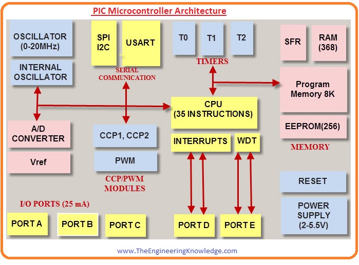
CPU
- The central processing unit is similar to the CPU of other controllers it comprises of ALU which performs the arithmetic operation and logic operation, CU which performs the control function, MU, etc.
- In MU or memory unit, different types of instruction are stored after processing.
- For controlling inner and outer devices linked with the controller control unit perform this function.
Memory Unit
- In the memory unit of the PIC controller, the memory used is ROM, RAM, and STACKs. All these are discussed here.
RAM
- RAM or random access memory unit is a volatile memory unit that stores data for small-time interval in their registers. There are two groups in which RAM is defined which comprises numerous registers.
- These registers are further categorized into 2 parts SFR and GPR.
GPR
- These registers perform a general function such as the multiplication of 2 numbers done by this register. Storing of numbers in other registers is done through these registers.
SFR
- According to their names, these registers perform some special functions. The function assigned to these registers is performed by these registers and does not do general functions.
ROM
- in this type of memory, data is stored permanently and retains data when power is off. It also is known as program memory where operators write a program and store it for a long time.
- This stored program is executed by the central processing unit of the PIC controller.
EEPROM
- In the ROM program can write only a single time but in the EEPROM we can write and erase written data numerous times according to our requirements.
Flash Memory
- Flash memory is like the EEPROM over which we can write, read, and remove data according to our requirements. Generally, this category of memory is used in the PIC controller.
PIC Input and Outputs PORTS
- There are 5 ports exits in this controller which are A, B, C, D, and E.
- Port A is a sixteen-bit port that can be operated as input and output according to the TRISA register status or Tradoc Intelligence Support Activity.
- Port B is an eight-bit port that can be used as input and output.
- Port C is an eight-bit port.
- Port D is an eight-bit port that operates as a slave port for linking to the microprocessor bus.
BUS
- Two types of buses exist in this controller first one is the data bus and the second one is the address bus.
- The sending and receiving of data is done by the data bus.
- While transferring data from memory address to the central processing unit from externally connected devices.
PIC18F4550 Pin Diagram

Features of PIC18F4550 MCU
Timer
- This module comes with a timer that is used for different uses such as pulse counting, and pulse measuring features.
- It has 16-bit timers Timer0, Timer2, and Timer3 and Timer1 is an 8-bit timer.
- To use these Timer modules they have their individual Control and Status Registers.
- With the use of a timer as a counter, there is a need of an external pulse connection with RA4 pin with Timer0 and RC0 with Timer1.
ADC
- There are 13 Channel ADC of ten-bit configured on this board.
- These components help for reading analog signals such as temperature, accelerometer, and transform in digital number
UART
- UART is used for communication between 2 devices in a serial way. Such as longer-distance communication performed with this component. UART helps to make communication of this component with GSM, GPS, and WiFI through use of different Baud rates like 9600,115200, etc. For UART communication there is Rx and Tx pin used
External Interrupt
- For external interrupt, the INT0, INT1, and INT2 pins are used and the interrupt detects the required incoming pulse and does certain actions. For this purpose, there is a need of a Positive edge Trigger or a Negative Edge Trigger.
Capture/Compare/PWM CCP Module
Capture–
- It is used for measuring the frequency, or duty cycle of the input pulse. Make the connection of the input pulse with the RC2 pinout
Compare
- It is for the generation of square waves and for that purpose put count in registers that make comparsion with the timer and when matches are produced it produces high or low pulse output at the RC2 pin.
PWM
- The main functions of PWM are to control DC motor speed, vary LED intensity, and produce sine waves.
Master Synchronous Serial Port
- It is serial interfacing used for communication with different devices or controllers. Such as serial EEPROMs, display drivers, A/D converters, shift registers, etc.
The working of Master Synchronous Serial Ports in two methods which are
I2C
- It is 2 two-wire communication protocol and comes with 2 wires, SDA and SCL. SDA and SCL are configured with PortB.0 and PORTB.1. Speed control is about 100 Khz-400 KHz. It is used for interfacing different features such as a Gyroscope a magnetometer.
SPI
- SPI is also a serial communication system and has four wires for communication SDI, SDO, SCK (Serial Clock), and SS’ (Slave select). It is employed for making communication between SD cards, ADC chips,
Different types of 8-bit PIC Microcontrollers
| Features | Baseline | Mid Level | Increased Mid Level | Advanced PIC18 |
| Groups | PIC10, PIC16, PIC12, | PIC10, PIC12 | PIC12Fxxx, PIC16Fxxx | PIC 18 |
| Memory | 3 KB | 14 KB | 28 KB | 128 KB |
| Data Memory | 138 Bytes | 368 Bytes | 1-5 KB | 4 KB |
| Performance | 5 MIPS | 5 MIPS | 8 MIPS | 16 MIPS |
| Features | ADC 8-bit, Internal Oscillator Comparator | UART. 10-bit ADC, I2C/SPI. PWM. | Peripheral communication. High Performance PWM with Time-Space | CAN USB,PLL Clock generator ETHERNET LIN |
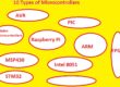
Top Types of PIC Microcontrollers Features
PIC16F877A
- 35 instructions sets
- 20MHz Frequency
- Working voltage 5.5V.
- packages: PDIP, TQFP, PLCC, and QFN.
PIC12F629
- 128 bytes of EEPROM.
- programmable pull-up resistors.
- interrupt
- 8 level stack
- Different addressing modes.
- Works at different temperatures.
- Different timers watchdog, up timer, and OST-oscillator start-up timer.
PIC16F886
- Frequency value 8-32 MHz.
- power-saving modes.
- EEPROM
- lash program memory with a hundred thousand writes/erase cycles.
- LIN, RS-485, and RS-232 Support
- 10-bit,11-channel A/D converter.
PIC16C58A
- 12-bit instructions
- 8-bit wide data path
- hardware registers
- Programmable code-protection
- high-speed CMOS EPROM/ROM technology Low-power
- Power-On Reset (POR)
- Watchdog Timer
- SLEEP mode
- Reset Timer
PIC 12F508
- 8 I/O pins.
- 4 MHz internal oscillators.
- Total 8 pins.
- 25 bytes EEPROM.
- 0.75 kb. Program Memory
- 8-bit time module
PIC 18F4520
- 2 Comparators
- 10 bit ADC
- Power on Reset
- Power up timer and OST
- voltage range 2V-5.5V.
- EEPROM and program memory.
What is the basic architecture of PIC microcontroller?
- PIC microcontroller is configured with Harvard architecture and provides different groups. The baseline and mid-level groups use 8-bit data memory configured, and high-end families use 16-bit data memory. The new PIC controllers are, PIC32MZ, is a 32-bit MIPS-based microcontroller.
How to identify PIC microcontroller?
- PIC microcontroller comes with external oscillators such as crystals or RC oscillators. For crystal oscillators the crystal is configured with two oscillator pins and the value of capacitors connected with the pin defines the working of oscillators.
What is the RAM of PIC microcontroller?
- The PIC 19 comes with the higest of 4096 bytes of data RAM. The data RAm for PIC 19 can be from 256 bytes to 4096 bytes. The data RAM space is based on two parameters General-Purpose RAM (GPR) and Special Function Registers (SFRs).
What is the function of PIC microcontroller?
- PIC microcontrollers is the best and most reliable instruments and are used for different project creation. They are low-cost and can easily buy at the local electronic shop. They are high power and come with features of 6 MIPS through the use of an inner oscillator block, and 16 times higher speed than other AVR microcontrollers.
How many ports are there in PIC microcontroller?
- It comes with 4 pins and 5 ports. PortA, PortB, PortC, PortD and PortE.
- It supported serial communication with 2 Pins TX and RX.
What are the disadvantages of PIC microcontroller?
- It comes with program memory that is not easy to access and is difficult to use. The length of PIC controller is also longer.
Which compiler is used for PIC microcontroller?
- MPLAB XC16 best compiler supported 16 bit microcontrollers (MCUs).
Read also:
That is a detailed post about PIC Microcontroller if you have any further queries ask in the comments. Thanks for reading. Have a good day.