 Hi, fellows welcome to another new interesting post. In today’s post, we will have a detailed look at Introduction to STM32F4. This module is comprised of thirty two-bit Cortex M4 central processing unit having FPU. It has a flash memory of one sixty-eight megahertz. It also comprises of flash memory, static random access memory, PSRAM, NOR memory units.
It also has a twenty by thirty-two bits backup register with four kilobytes of static random access memory as backup. In today’s post, we will have a look at its working, features, pinouts, and some other related terms. So let’s get started with Introduction to STM32F4.
Introduction to STM32F4
- The STM32F4 belongs to the family of thirty-two bit ARM Microcontrollers which is created by the STmicrocontroller.
- The family of STM32F provides different features but all these controllers use a microcontroller of thirty-two bits. The STM32F4 provides eighty-four megahertz clock speed. has a flash memory of five hundred twelve kilobytes, the static ram of having space of ninety-kilo byte.
- There are numerous pinouts exits on this module which can be operated as inputs and outputs and can also be used to provide programming to the board.
- There are numerous applications provided by this module different categories of communications devices can be attached with this controller for linking of different types of electronic instruments such as detectors, and motors. etc.
- This board comprises of numerous other devices used for communication and interfacing of different projects without any use of the external device.
- This module also comes with some other components such as digital to analog converter, analog-to-digital converter, the port of sound, all these components make is the complete board.
Features of STM32F4
- These are some important features of STM32F4 which are described here with detail.
- It comprises of ARM thirty-two-bit Cortex central processing unit with a frequency of one eighty megahertz
- It has RAm having a space of one ninety kilobytes.
- The flash memory of one megabyte is exited in this module.
- There are functioning voltage range for this module is five volts.
- there is no debugging port exits in it.
- The power supply to this module can be given by the USB port.
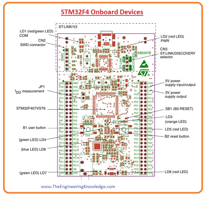
- There are 4 user light-emitting diodes that exist on this board in the color range of orange, green, red, and blue.
- 2 push buttons exist on this board first is for reset purposes and the second one is for the user.
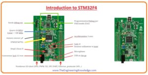
Pinout of STM32F4
- The pinouts of STM32F4 are described here with detail. The pins of this module are divided into two parts which denoted in the figure as P1 and P2 and both comprise of five ports A, c, D, E, and H which are used to perform different functions.

Power Pinouts
- There is numerous pinouts exist on this board for delivering the five volts to the different component connected.
- These used as input power pins in the groups P1 and P2 are given as Third and the fourth pin in group P1 and third and fourth pinout in group P2 are used as input pinouts.
- The pinout provides power as output in the range of 3 volts and five volts.
- the pins which give five volts are pin three and four in group P2 and pins that provide three volts are pins 5, 6, 15, and 16 in group P2.
GND Pinout
- In group P1 the pinouts used as the ground are 1, 2, 5,23, 49, and 50. and pins used as a ground in group P2 are 1, 2, 49, and 50.
Oscillator Pinout
- There is no inner crystal clock pulse in this module. There are 4 outer clock pulse pinouts it has 2 operate for thirty-two-kilohertz crystals and 2 for large-value frequency crystals.
- The pinouts used as oscillators are lies in group 2 and named as.
- GPIO7, GPIO, GPIO GPIO10
GPIO Pinouts
- Six ports exist in this board which are denoted as A, B, C, D, E, and H all these ports have inner pull-up resistance and operate as inputs and outputs.
- These pins exit in group P1 are GPIO7 to GPIO22 and GPIO24 to GPIO47 and these pinouts in group P2 have a range of GPIO7 to GPIO21.
USART Communication Pins
P1 Header:
- USART2 TX = GPIO14
- USART2 RX = GPIO13
- USART3 TX =GPIO34, GPIO40
- USART3 RX = GPIO37, GPIO42
- USART4 TX = GPIO12
- USART4 RX = GPIO11
P2 Header
- USART1 TX = GPIO23, GPIO44
- USART1 RX = GPIO24, GPIO41
- USART2 TX = GPIO29
- USART2 RX = GPIO30
- USART3 TX = GPIO37
- USART3 RX = GPIO38
- USART4 TX = GPIO37
- USART4 RX = GPIO38
- USART5 TX = GPIO35
- USART5 RX = GPIO34
- USART6 TX = GPIO47
- USART6 RX = GPIO48
SPI Communication
- SPI2 MOSI =GPIO9
- SPI2 MISO = GPIO10
- SPI1 SCK = GPIO15
- SPI1 MOSI =GPIO17
- SPI1 MISO =GPIO18
- SPI2 SCK =GPIO34
- SPI2 SCK = GPIO37
- SPI2 MISO =GPIO38
- SPI2 MOSI GPIO39
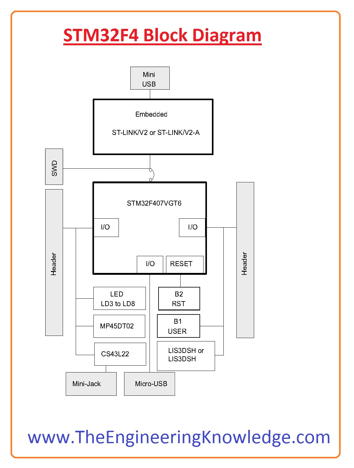
STM32F4 Block Diagram
- Now we discuss the block diagram of this board and know about the different components used in this module.
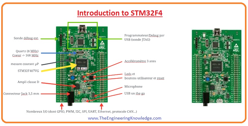
STM32F4 Onboard Devices
Audio Port:
- There is audio pinout exits on this board but with that, it has an audio port which used for linking of outer audio devices.
Universal Serial Bus
- The USB of this module is like OTG which can be used only for programming the MCU. the voltage range for USB should be of five volts and a larger voltage will damage it.
Current Usage Pinout
- There is a current usage pinout that exists on this board used jumper and can be eliminated for calculation of current through the ammeter.
Accelerometer:
- For the measurement of force exerted on the board, there are three line accelerometers is connected on the board.
- It protects the board when it is used in the robotic and such projects in which movement is involved.
Debugging Port
- For debugging this board there are JTAG and SWD ports that exist on this board.
Applications of STM32F4
- These are some important applications of these modules which are described here with the details.
- It is used in different types of embedded and robotic projects.
- As it provides numerous functions it is used in industries for controlling machines.
- It is also used in sound communication projects.
FAQS
What is the difference between STM32F4 and STM32F7?
- STM32F7 comes with 462 DMIPS and 1082 CoreMark for performance with floating point double speed than STM32F4 series and an ST follows real-time memory accelerator. STM32F7 enhances performance but does not affect power efficiency.
What is the difference between STM32 F3 and F4?
- The F3 and F4 chips come with different features but the board also has different uses. The F3 series of controllers comes with easy to afford as compared to Fr and comes with less program memory not have ethernet features and uses one USB port.
What is the difference between STM32F412 and STM32F413?
- STM32F412 features are high RAM and flash memory and comes with peripheral sets such as 10 UART, 3 CAN, SAI interface and low-power timer, 2 DACs, and 2 DFSDM with 6 filters.
Is STM32 more powerful than Arduino?
- ARM Cortex M is a processor that has good performance and high efficiency as compared to RISC. STM32 has good speed and performance than Arduino.
What is the difference between STM32H7 and STM32F7?
- The basic difference between STM32F7 and STM32H7 is their processing power and clock speed. STM32H7 controller has dual Cortex-M7 and Cortex-M4 cores. Provides high clock speed and better performance the STM32F7 series uses a single Cortex-M7 core.
What are the different models of STM32?
- STM32 F0.
- STM32 F1.
- STM32 F2.
- STM32 F3.
- STM32 F4.
- STM32 F7.
- STM32 G0.
- STM32 G4.
Does STM32F4 have EEPROM?
- All types of STM32 MCUs come with self-programmable flash memory. If there is a need to store settings, we can store in part of Flash. ST offers a library for performing EEPROM emulation over STM32F4.
What are the components of STM32?
- The STM32 board comes in different series that are based on 32-bit ARM processor cores, Cortex-M7 Cortex-M0, Cortex-M0+, Cortex-M3, Cortex-M4, , and Cortex-M33.
- It also has a RAM processor core, flash memory, Static RAM, debugging interface and other components
Read also
So friends it is a detailed post about STM32F4 if you have any further query ask in the comments. Thanks for reading