 Hi reader welcomes to the website. In this tutorial, I am going to share info about Introduction to Instrumentation Amplifier. The instrumentation amplifier is also called an instrumentational amplifier and written in short form as In-Amp. This amplifier is the category of such differential amplifier whose input is linked to the buffer amplifier this configuration makes it favorable for testing of different devices. This module comprises of less level dc offset, less drift, less noise distorted sound.
The graphical representation of this amplifier is like the normal operational amplifier but in practically it comprises of three operational amplifiers. In this post, we will discuss its configuration, operation working, and some other related parameters. So let’s get started with Introduction to Instrumentation Amplifier.
Introduction to Instrumentation Amplifier
- The instrumentation amplifier operation based on differential voltage gain rule which used to amplify the difference among 2 voltage given at input terminals.
- The basic usage of these modules is to do amplification of small level signals which are assembled with the heavy common-mode signal.
- The main features of this amplifier is its large value impedance, large common-mode rejection less output offset, and less value impedance at the output.
- The circuitry of this amplifier comprises of ics which consists of 3 operational amplifier circuits and numerous resistances.
- The value of voltage gain of this device is adjusted with the use of exterior resistances.
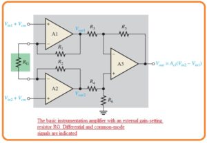
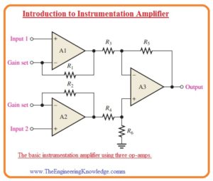
- The circuit configuration of this module is shown in the below figure.
- In this circuit configuration, the operational amplifier denoted as A1 and A2 are in a non-inverting arrangement that offers large value impedance and voltage gain.
- The operational amplifier denoted as A3 is working as a unity gain differential amplifier that has largely precise resistances which has values (R3 = R4 = R5 = R6).
- The gain setting resistance is linked eternally you can see in the below figure.
- The operational amplifier A2 gets the differential input signal at the non-inverting terminal and do amplification of this signal with the voltage gain value of
Av = 1 +R1/RG
- At the operational amplifier A1 the input voltage is provided at the inverting terminal with the use of operational amplifier denoted as A2 and
- Op-amp A1 also has as an input signal to its inverting input through op-amp A2 and path created by the resistance R2 and RG.
- The signal given at input get amplified through the operational amplifier A1 with the voltage gain value of.
Av = R1/RG
- The net closed-loop gain of this amplifier is given here.
Acl=1 +2R/RG—-A
- The equation A indicates that the gain of this amplifier can be adjusted through the value of outer resistance for fixed value of resistances R1 and R2.
- The outer gain setting resistance value can be measured for required voltage gain with this equation.
RG=2R/(Acl-1)
Application of Instrumentation Amplifier
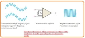
- The most common use of this module is in the amplification of such a signal which has very small value differential voltage which are residing at the common-mode voltage which has large value over the signal voltage.
- The main application of this is such a condition in which values are detected through the distant instruments like temperature and pressure measuring devices and consequent less value electric signal is move through the line which generates a common-mode signal in the line.
- The instrumentation amplifier existing at the other end of the line should do the amplification of small value signals through the distant sensing device and remove the highly common-mode signal.
- The below figure explains this process.
Certain Instrumentation Amplifier
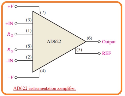
- Till now we have discussed the basics of the instrumentation amplifier now we discuss the certain component which iss AD622 which is shown in the below figure.
- In this figure, the pinout numbers of integrated circuits are mentioned for reference.
- The structure of the instrumentation amplifier comprises of 3 operational amplifiers which we have seen in first figure.
- Some parameters of this module are described here.
- The value of voltage gain be set from two to one thousand with the use of outer resistance denoted as RG.
- The gain is unity having the absence of outer resistance.
- the value of input impedance is ten Giga ohm.
- The value of common-mode rejection or CMRR is least value of sixty-six decibels.
- If the value of the common-mode rejection ratio is larger than the rejection of common-mode voltage is of high quality.
- The bandwidth is AD622 is eight kilohertz having gain of ten and slew rate of 1.2 volts per milliseconds.
Adjustment of Voltage Gain for AD622
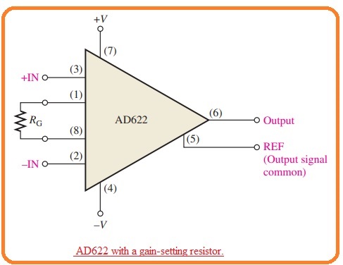
- To get value of voltage gain larger than the unity there is outer resistance is used as shown in the below figure.
- The resistance is linked with the pinouts one and eight. There is no need of resistance for unity.
- The value of RG is chosen for the resultant gain according to this formula.
RG = 50.5 kΩ/(Av – 1)
Gain vs Frequency
- The graph shown in below figure indicates how the value of gain changes according to the frequency for the gain value of one, ten, hundred and thousand.
- From the graph you can see that the bandwidth reduces with the gain increment.
Effects of Noise at Applications of Instrumentation Amplifier
- For sensing of temperature, strain, pressure and some other parameters numerous transducers are used.
- The common applications of these amplifiers are in such applications where less value voltage are generated through the transducers and in such industries where large sound is generated and longer cables are attached with the output of transducers and input of amplifiers.
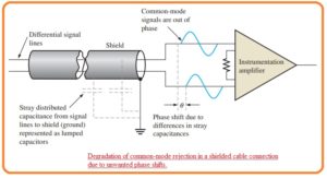
- The sound or noise in the form of common-mode signals obtained from the outer devices can be reduced but not completely minimized with the use of coaxial cable which comprises of differential signal cables are consist of metal mesh sheath that is known as a shield.
- In such a condition where electric sound is generated any common-mode voltage which is produced at the signal lines are eliminated since both input terminals of amplifiers have a similar common-mode voltage.
- When there is such cable that has sheath is used there is stray capacitance is separated about the distance among every signal path and covered sheath.
- The difference between these stray capacitance especially in case of large value of frequency causes the phase shift among the 2 common-mode signals which are shown in the below figures.
- It caused the decrement in the common-mode rejection of amplifier since the 2 signals has different phases and not cancel out one another.
- therefor the voltage generated at the input terminals of amplifiers.
What is Shield Guard
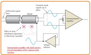
- The guarding is a process which used to decrease the factor of sound at the common-mode operation of instrumentation amplifier working in a serious situation through connecting the common-mode voltage the covered sheath of coaxial cable.
- The common-mode signal is given back to the shield through the voltage follower configuration which is shown in below figure.
- The function is to minimize voltage difference among the signal lines and shield, that reduces the leakage current and cancel out the efect of distributed capacitance therefore the common-mode voltage are similar in both lines.
- The voltage follower is less impedance source which runs the common-mode signal at the shield to decrease the voltage difference among the signal lines and sheath.
- When the value of voltage among the every signal path and sheath is 0 there is no existence of leakage current and the value of capacitance reactance is very high.
- The infinite value of capacitance reactance indicates that capacitance is 0.
Certain Instrumentation Amplifier having Guard Output
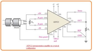
- Some types of these amplifiers are arranged in such a way that they offer a shield guard driver.
- The specific integrated circuit amplifier offers an inner created guard output that is designed for special conditions.
- The instance of this device is AD522 which is shown here.
- That is a precisely integrated circuit instrumentation amplifier created for applications that required larger correctness in case of severe operating situations and having a small value of signals.
That is detailed post about Instrumentation Amplifier i tried my level best to make simple this post if you have any further query ask in comments. Thanks for reading have a good day.


