 Hi, reader hope you all are having fun in your life. In today’s post will have a detailed look at Introduction to Isolation Amplifier. The isolation amplifier is a type of amplifier which used to offer dc separation among the input and output side. It is helpful in such an environment where dangerous power leakage or large voltage transients exist to provides protection to the people and sensitive elements linked with the circuits.
The common usage of this amplifier is in medical devices, different types of power plant devices, industries processing devices, and automated testing devices. In this post, we will discuss its circuit, operation, and some other factors. So let’s get started with Introduction to Isolation Amplifier.
Capacitor-Coupled Isolation Amplifier
- The isolation amplifier is such a module that comprises of 2 types of circuits or stages that are separated electrically.
- These 2 stages are input and output that is isolated from one another through an isolation barrier which processed the signal to coupled about the isolation border.
- In some types of isolation amplifiers, there is the optical coupling or transformer coupling is used to separate two circuits.
- In some other types of isolation amplifiers, there is a capacitor is used for separation.
- Every circuit or stage comprises of its won power source and ground terminal due to this there is no common electric path among them.
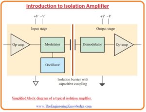
- In the below figure the normal figure of an isolation amplifier is shown.
- You can see that there is 2 ground symbols are used for denoting the concept of stage isolation.
- The input part or stage comprises of the amplifier circuit, oscillator and modulator circuit.
- Modulation is the procedure through which a signal which comprises of data get a modification in another type of signal, like frequency, amplitude, therefore, data exists in the first signal is also existing in 2nd
- For this condition, the modulator comprises of square wave oscillator which generates large value frequency for modification of real signal.
- The capacitor having less value of capacitance in the separation barrier is used for coupling the less value frequency modulated signal or dc voltage from the inner side to the outer side.
- In the absence of modulation, there is a need of capacitor which has a large value of capacitance and it causes to decrement in the isolation among 2 stages.
- The outer stage comprises of demodulator which gets the real input signal from the modulated signal that converts the real signal in the original form.
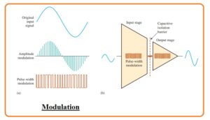
- The large frequency oscillator output shown in the above figure can be of amplitude or pulse width modulated through the signal from the input amplifier.
- In the case of amplitude modulation, the amplitude of oscillator output is changed resultantly to changes in the input signal which is shown in the below figure denoted as a.
- In this figure sinusoidal signal is used for description.
- In the case of pulse width modulation, the duty cycle of the oscillator output changed through varying the pulse width according to the changing in the input signal.
- The isolation amplifier using pulse width modulation is shown in the below figure denoted as b.
- Though it uses a little bit complicated procedure interiorly the isolation amplifier is the only amplifier and is easy to usage.
- If distinct dc power source and input signal are given an amplified signal at output is generated.
- The isolation process is its own non seen procedure.
Transformer-Coupled Isolation Amplifier
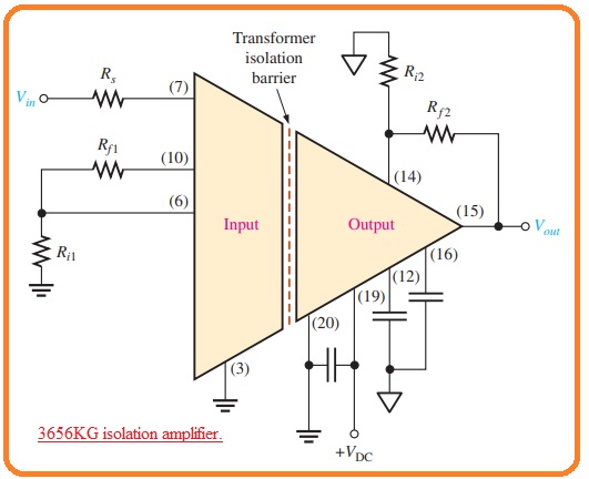
- The common example of an isolation amplifier is the Texas instrument 3656-kilo gram which comprises of transformer for isolation of 2 stages.
- Contrary to the ISO124 that comprises of certain value of unity gain the 3656 kilogram offers for outer gain variation of both circuits.
- The circuit diagram of 3656-kilo gram having outer gain resistance and decoupling capacitor is shown in the below figure.
- The voltage gain of both the input side and output side can be adjusted through outer resistance linked shown in the figure.
- The value of gain at the input stage is given here.
Av1= Rf1/Ri1+ 1
- The value of gain at the output stage is given here.
Av2=Rf2/Ri2+1
- The net amplifier gain is the multiple of two gain obtained at input and output.
Av(tot) = Av1Av2
Applications of Isolation Amplifier
- As above we discussed that isolation amplifier is used in such applications that do not require common ground terminal among transducer and processing circuitry for such circuit where interlinking among sensitive devices is needed.
- In industries such as chemical, nuclear, and metal processing for instance mv voltage are present in the existence of large value common voltage which has value in the range of kVs.
- In this category of circuits, the isolation amplifier can amplify less value voltage which exists in the noisy devices and generates a safe value output which can be used for computers, laptops, etc that are sensitive modules.
- There is an important application in medical devices.
- In medical devices in such applications where body operation are involved like heart rate and monitoring of blood pressure, there is very less value signal are linked through large common-mode signal like sixty-hertz power line pickup from the skin.
- In these circumstances in absence of isolation dc leakage or damaging of devices can be disastrous.
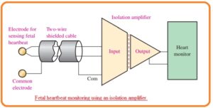
- In the below figure, there is a diagram of isolation amplifier in a cardiac monitoring application.
- In this condition signal of heart that has small value are linked with the large common-mode signal produced by the noise of mussels, electrochemical sound, residual electrode voltage and sixty-hertz power line picking up from the skin.
So friends that is detailed post about Isolation amplifier if you have any further query ask in comments. Thanks for reading have a good da


