 Hello friends, I hope you all are doing great. In today’s tutorial, we will have a look at How to Troubleshoot Power Amplifiers. Troubleshooting is the process to solve the problem is used to repair damage to different instruments, machines or circuits. In the previous tutorial, we discussed different amplifiers such as class A, Class B, and Class C power amplifiers.
In today’s post, we will have a detailed look at the troubleshooting and repair of power amplifiers. We will perform troubleshooting for class A and class AB amplifiers. So let’s get started with How to Troubleshoot Power Amplifiers.
What is a Class AB Amplifier?
- The Class AB amplifiers have two types of amplifier circuits: Class A and Class B amplifiers. It is used for audio circuits, such as the sound signal of a microphone amplified with these circuits.
- That amplifies employs class A and class B for removing distortion and increases power efficiency. The working of class A state is a linear mode, amplifying a signal through low distortion with loss of high power when no input is given.
- Class B part of AB amplifies the signal if the signal is larger as compared to a certain threshold value; reducing power used causes crossover distortion.
- For AB amplifier class bias, a part is lower than the peak output value of the input, so it handles low signals, and the class B stage works for high-level signals.
Working of Class AB Amplifier?
- Working class AB amplifiers come with class A and class B amplifiers to get needed low distortion and high power efficiency.
- The class A stage and class B stage make up two main phases of class AB amplifiers. If there is no input signal, the Class A part uses high power when it operates in a linear component and amplifies the input signal with low distortion.
- The Class B reduces power usage by adding crossover distortion because it amplifies the input signal when over a certain threshold.
- The bias of clas A stage of class AB amplifies below the input signal peak output value. Class B phase gets high-value signals, and class A stages handle low signals. The class A part amplifies the signal when the input signal has weak strength and class B is in an off state. Class B operates and gets applications when input signals cross a certain threshold value and provides class A to use low power.
- The Class AB amplifiers can produce high-quality sound with low distortion and provide high power efficiency through the use of Class A and Class B amplifiers.
Class AB Amplifier Applications?
Audio systems:
- It is used in vehicle sound systems, audio amplifier circuits, and also as part of the audio system for providing high-quality sound.
Instrumentation amplifiers:
- It uses Class AB amplifiers for accurately measuring small signal values and is good for the amplification of low-strength signals.
Communication systems:
- For increasing signal strength in communications, these amplifiers are used, such as in TV and radio signal amplification. They reduce distortion and strength losses.
Power amplifiers:
- It is used for power amplification for high-power circuits, like large-scale audio circuits.
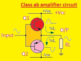
Class AB amplifier circuit
- The class A stage and class B are main parts of class AB amplifier circuits. The class B operates in a non-linear way and does signal amplification when it has a certain threshold. The Class A is a biased continuous current source for operating in the linear region.
- The class AB amplifier circuit seen here
- The input signal is given to the base of transistor Q1. The continuous current source is employed for biasing transistor Q1 that operates in class A.
- The base pin of transistor Q2 that operates in class B gets a signal from Q1 after it has been amplified.
- Q2 is off state, and class A does amplification if the input signal does not have strong strength. Q2 activates and gets amplification if the input signal amplitude increases, providing class A phase to use low power.
- Load is resistant and connected with the output signal of the circuit, which is taken from the Q2 collector. The RL and collector resistance Q2 affect gain amplifiers.
How to Troubleshoot Power Amplifiers
- First of all, we discuss the troubleshooting of class A amplifiers.
Class A Amplifier Troubleshooting
- The proper working-class amplifier is shown in below figure where a fine sine wave is generated when the input voltage is applied.
- Let’s take 4 faulty signal output waves which are normally occurred.
- In figure denoted as ‘a’ oscilloscope shows a dc level equal to the dc source voltage denoting that the transistor is the cutoff mode.
- The 2 main reasons for this condition are given as.
- The PN junction of the transistor is open.
- Resistance R4 of the circuit is open and stops current from the collector and emitter.
- In the figure denoted as ‘b’ the oscilloscope shows a dc signal at the collector almost equal to the voltage of the emitter.
- The main reasons for this state are given as.
- The transistor is a short circuit with transistors.
- Resistance R2 is an open circuit that caused the transistor to be in the saturation region.
- In 2nd condition, enough high input signal can cause saturation at the negative peak which causes short pulses at the output.
- In figure denoted as ‘c’ oscilloscope display that an output signal which shows that the transistor is in cutoff for a small part of the input signal.
- The 2 main reasons for this are.
- The position of Q point has changed down due to high variations in the tolerances of resistance.
- Resistance R1 is an open circuit biased transistor in the cutoff region.
- The figure denoted showed that the input wave is enough to cause a cutoff region for a small part of the signal.
- In figure denoted as d oscilloscope show an output signal which shows that the transistor is in saturation by letting a small part of the signal.
- The reasons for this are.
- Faulty value resistance has changed the position of Q-point towards saturation.
- Resistance R2 is an open circuit that causes the transistor to be in a saturation region and the input wave brought out saturation for a small part of the signal.

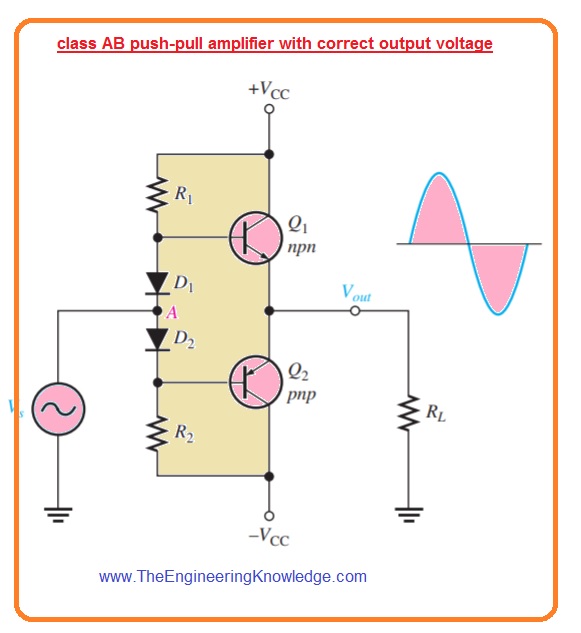
Class AB Troubleshooting
- In the below figure class AB push-pull amplifier is shown the output of ac signal is also shown correspondent to an ac input signal.
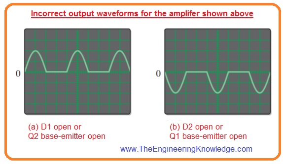
- The 2 faulty output signal is shown in the below figure.
- The figure denoted as show that only the positive half of the input wave is exits at the output.
- Then the first main reason is that diode Di is open. If it is an error the positive half of the input wave is forward biases the diode D2 and causes transistor Q2 to operate.
- The second possible cause is that the base-emitter junction of transistor Q2 is open so a positive half cycle of input signal exits on the output as transistor Q1 is operating.
- The waveform shown in figure b indicates that only the negative half of the wave exists at the output.
- The first fault for this is that diode D2 is an open circuit. If this is error negative half of the input wave forward biases diode D1 and put the half signal at the base of transistor Q1.
- The second fault is that the base-emitter junction of transistor Q1 is open due to the negative half of the input wave display at the output since transistor Q2 is operating.
Read also
- Introduction to Class D Amplifier
- CLASS B and Class AB Push Pull Amplifier
- Introduction to Class A Amplifier
- Difference Between An Operational Amplifier and Comparator
So, friends, it is a detailed post about How to Troubleshoot Power Amplifiers if you have any questions about it ask in the comments. Thanks for reading.

The article is very current for what we live, and life is getting harder.
I have made a way to have a real job at home, without cheating,
maybe it will help someone.