 Hello friends I hope you all are doing great. In this post, we will have a detailed look at Introduction to TRIAC. TRIAC are electronic devices that employed in applications where ac power control needed. They use to switch the high value of voltages and larger current during both polarities of AC signal. Lights used in homes comprise of dimers that consist of triac also used in the regulation of motor electronic switches it used.
It also works for the less to intermediate power circuits of switching elements in place of thyristor they are used in some circuits. In this post, we cover details about its working, construction applications, and related parameters. So let’s get started with Introduction to TRIAC.
Introduction to TRIAC
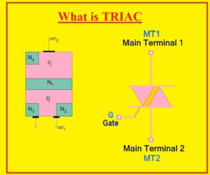
- The TRIAC also called bidirectional triode thyristor, or tri diode for AC consists of 3 terminals through them current can flow any direction gets triggered.
- TRIAC belongs to the thyristor family and also has some features of the relay that also show specifications related to SCR.
- The main difference between TRIAC and SCR is that current flows in SCR only a single direction and in TRIAC in two directions.
- TRIAC can be operated through the application of both negative and positive polarity voltage but SCR operates from positive polarity.
- After trigger both retain their operation either supply is disconnected from the gate terminals till the point the main current loses to value less than the specific point known as holding current.
- GTO or gate turn off thyristor shows similar features to TRIAC with that offers larger regulation and control through tuning off in case there is a gate that has zero signal.
- Due to two-direction operation, it is used for switching of AC with that used for triggering at a regulated phase angle of ac in the circuitry which permits control of average current passing towards the load.

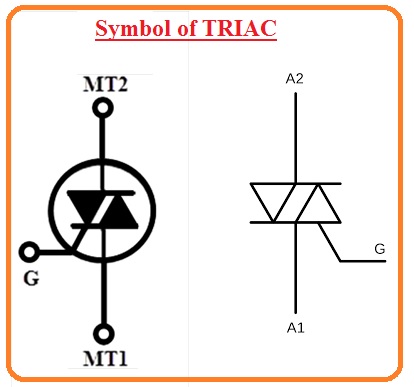
Symbol of TRIAC
- The TRIAC is a combination of 2 equivalent SCRs connected in reverse parallel combination their gate terminals are lined to creates one single gate.
- Here you can see the triac symbol that has 3 terminals first one is MT1 second one is MT2 and the third one is Gate.
- MTI called anode and MT2 is known as the cathode.
Construction of TRIAC
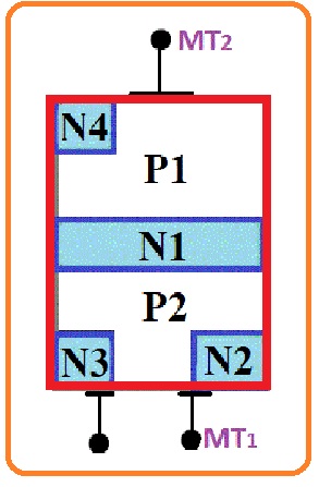
- In the below figure, we can see the construction of TRIAC. It has 4 layers which comprise of further 6 doping areas. The gates of this device are created in such a technique that has an ohmic connection to the N and P parts due to this assembly TRIAC gets triggered from the negative and positive supply.
TRIAC Operation
- TRIAC starts conduction if the voltage given lies in the breakdown voltage that the commonly used technique for TRIAC is offering a gate pulse through positive or negative supply.
- If the value of the current is large then a smaller quantity of voltage is good to on TRIAC.
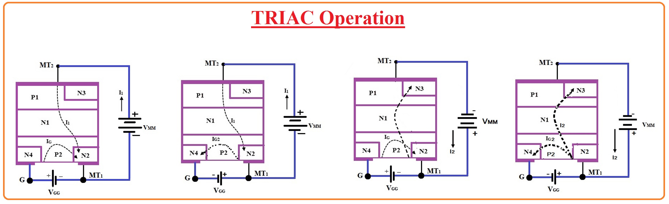
- There is TRIAC is a two-directional device that comes on with the two polarities given at the gate so it runs in the 4 different operation states or four quadrants.
- These 4 modes of operation are listed here.
- In first mode, the MT2 has a positive state reference to the MT1 terminal and the gate is positive according to MT1.
- In 2nd mode MT2 is positive according to MT1 gate polarity is negative according to MT1 terminal
- MT2 terminal in the third mode is negative according to MT1 and gate is negative according to MT1.
- In the fourth mode there is MT2 is negative according to MT1 and the gate is positive according to MT1.
In the below figure four modes of operation of TRIAC are shown in below figure and the current direction is also shown in the figure.
TRIAC VI characteristics
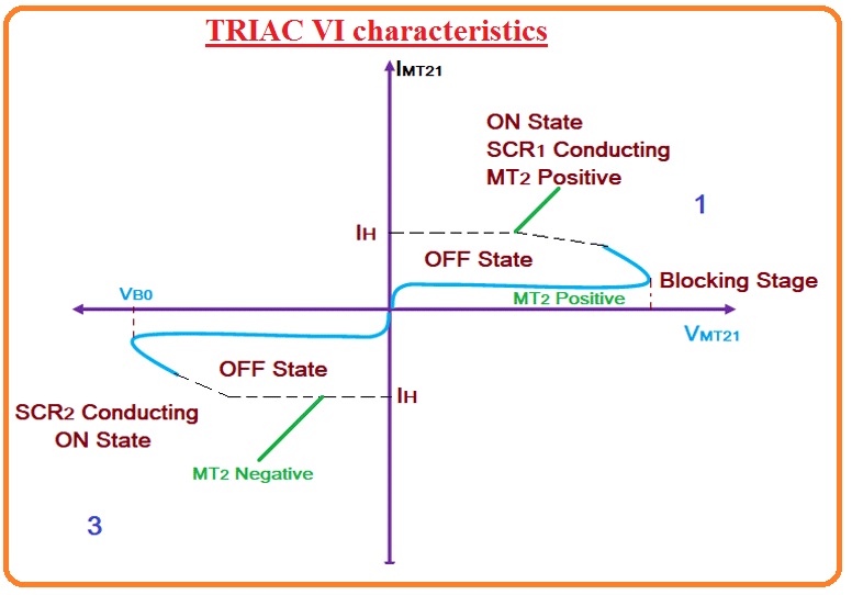
- As this device is two-directional so its VI curve lies in the ist and thrid quadrant which is like to the VI characteristics of a thyristor.
- If the voltage level at MT2 is positive according to MT1 terminal then TRIAC is operating in the forward mode of operation.
- In the starting phase resistance offered by the TRIAC, there will be less leakage current passing from the component as given voltage is less than the breakdown voltage.
- If the voltage rises and it moves to the breakdown voltage the TRIAC is getting on and the large current flows from the TRIAC.
- With rising the voltage of the component, the TRIAC gets on by offering a gate signal if the voltage provided has less value than the breakdown voltage.
- Similar work can be done in the negative polarity of the TRIAC which will be an opposite state of the similar curve shown in the negative quadrant.
- The voltage given over the TRIAC conduct will rely on the gate current given to the TRIAC.
- If the gate current is large so voltage needed to run the ON TRIAC will be less.
- The characteristic curvature that can seen working of TRIAC is the first and third quadrants.
Read also:
- Difference between scr and triac
- Introduction to BT136-600E TRIAC
- Introduction to BTA12 TRIAC
- Introduction to BT136 TRIAC
- Introduction to BT139 TRIAC, Working, Pinout & Application
- Difference between GTO and SCR
Faqs
- The TRIAC is a semiconductor device that is used in power regulation and switching applications.it is used in switching phase control brilliance control in lights, speed control in fans and motors, etc
- Triac switches are used with heavy, inductive loads and different applications where AC voltage circuits are used. These switches are used for power control in AC systems having high power switching needs.
- TRIAC conducts current in any direction when its gate is triggered. It is also called a bidirectional triode thyristor. Its main types are numberless, alternator, internally triggered, logic gate, and standard that are chassis, surface or through-hole mount.
- DIAC is a diode for AC that allows current to flow in two directions when voltage is larger than break-over voltage is applied. TRIAC is a bidirectional SCR, that has features of conducting in both directions when triggered with a gate pulse.
- The TRIAC is a bidirectional 3-electrode AC switch that helps electrons to flow in any direction. It is equivalent to two SCRs connected in reverse parallel configuration with gates connected. The TRIAC is triggered is conduction in both directions with gate signals like SCR.
- It has a different voltage range from 600 to 800 V and up to 1200 V for some industry devices, ST‘s portfolio covers medium-power AC loads with 1 to 50 A triacs.
- The circuit symbol of TRIA comes with 3 electrodes of devices like anodes and the gate.
- Though not all TRIA devices are made in the same way, they come with two SCrs, that are connected in antiparallel to each other through a cathode and anode.
- TRIA comes with 4 layers and 3 layers of power semiconductor devices. The terminals of TRIAC are (MT1), main terminal 2 (MT2), and a gate terminal.
- Thyristors are solid-state devices and relays are electromechanical device
- TRIACs come with a lower voltage and current rating than SCRs, The TRIACs are best for controlling lower-power AC loads like lamps and heaters, while SCRs are preferred for high-power applications like motor control and industrial machinery.
That is a detailed post about TRIAC if you have any further queries ask in the comments. If you have any further query ask in a comment. Thanks for reading have a nice day.